Cross flame holder for rotor engine

A flame stabilizer and rotary engine technology, which is applied to machines/engines, mechanical equipment, gas turbine devices, etc., can solve the problems of narrow adjustable range of airflow velocity in combustion chamber, limited size of pre-combustion stage flame space, and high processing accuracy. Achieve the effect of ensuring combustion stability, increasing the flame surface area, and increasing the heat release rate

Inactive Publication Date: 2010-12-08
BEIHANG UNIV
View PDF5 Cites 0 Cited by
  • Summary
  • Abstract
  • Description
  • Claims
  • Application Information

AI Technical Summary

Problems solved by technology

The domestic patent (Patent No.: 200710176096.7) on the high-level flame stabilizer introduces the tower flame stabilizer for the rotary engine, but the tower flame stabilizer for the rotary engine has great limitations: firstly, its structure is relatively complicated, The processing requires high precision; secondly, the adjustable range of airflow velocity in the combustion chamber is narrow, and the internal flow loss is large, which cannot be applied to the situation of high Ma number; moreover, the space size of the generated pre-combustion flame is limited and cannot be used in a wide range Provide an effective ignition source for the main combustion stage in the space

Method used


Image

  • Cross flame holder for rotor engine
  • Cross flame holder for rotor engine
  • Cross flame holder for rotor engine

Examples


Embodiment Construction

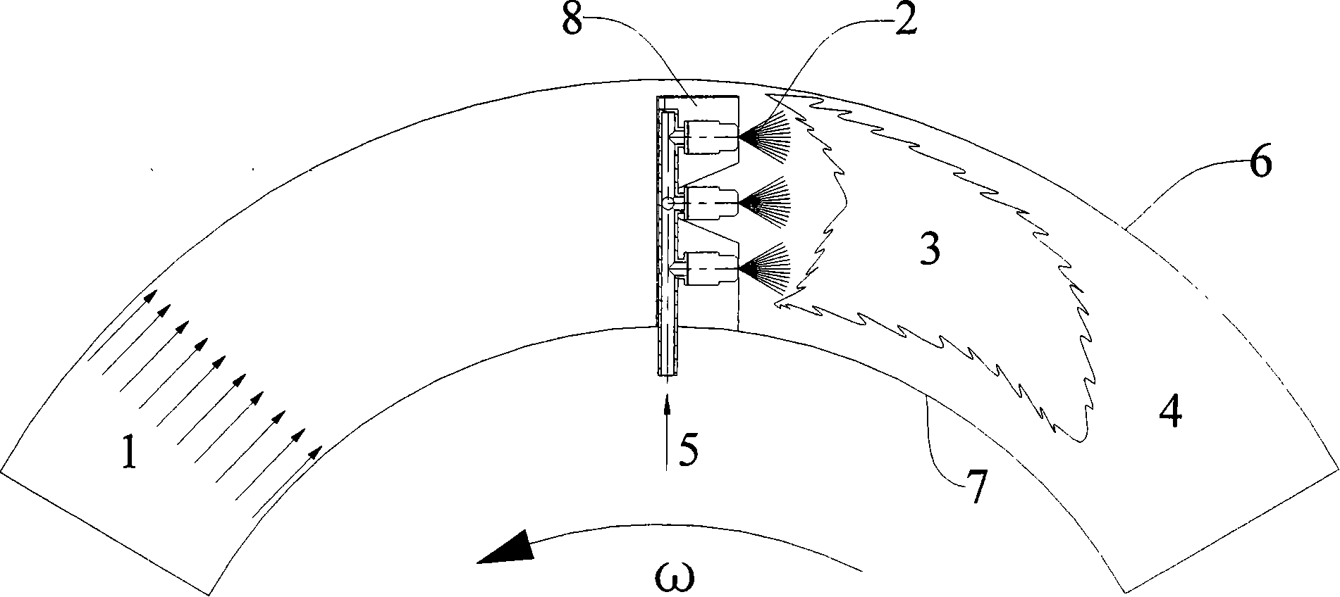
[0030] Such as figure 1As shown, according to the different designs of the rotary engine, the casing 6 outside the combustion chamber is fixed or rotates, while the casing 7 inside the combustion chamber rotates with the engine rotor at an angular velocity ω. The main flow 1 of the combustion chamber flows into the combustion chamber at a certain relative speed, and the relative Mach number of this flow in a typical rotary engine is above 0.2. The main flow 1 of the combustion chamber flows through the cross flame stabilizer 8, forming a local low-speed recirculation zone behind it, and fuel is supplied to the cross flame stabilizer 8 through the fuel supply 5, and is sprayed into the low-velocity recirculation zone in the form of oil mist 2 to carry out Oil and gas are mixed to form a stable pre-combustion flame 3. Since the entire combustion chamber rotates with the rotor, and the reference coordinate system is fixed on the rotor, there is a centrifugal force field in the c...


PUM


Abstract

The invention relates to a cross flame stabilizer used for a rotary engine which consists of a trough for stabilizing fire and an oil feeding device, wherein, the oil feeding device is positioned in the trough for stabilizing fire; the trough for stabilizing fire takes the shape of a cross, is composed of a horizontal two-dimensional V-shaped trough and a vertical two-dimensional V-shaped trough,and can generate large-scale stable precombustion level flame which can cross the height and width of a combustion chamber; the center of the cross flame stabilizer is positioned at high position of the combustion chamber, the precombustion level flame at high position is spread to the low position by using strong centrifugal effect, so as to provide a stable ignition source for the main combustion level; a split flow cover at the front end of the trough for stabilizing fire adopts a rounding structure, so as to reduce the flow resistance loss of the main stream; the oil feeding device adoptsa centrifugal spray nozzle or a projective spray nozzle to feed oil, besides a fuel injection nozzle arranged at the center of the cross flame stabilizer, a plurality of spray nozzles can be arrangedalong the trough for stabilizing fire to ensure the joint flame and spread of the precombustion level flame; the cross flame stabilizer of the invention has simple structure, can generate large-scalestable flame by fully using influence of strong rotating centrifugal effect on the spread of flame, thus improving the combustion stability and the combustion efficiency of the combustion chamber of the rotary engine.

Description

technical field [0001] The invention relates to a flame stabilizing device of a rotary engine, which can provide a large-scale stable ignition source for the main combustion stage in a rotating strong centrifugal force field, and can ensure stable and efficient combustion under high-speed rotating conditions—a cross flame stabilizer . Background technique [0002] Foreign countries have developed a new concept engine, a ramjet rotor engine, which integrates ramjet engine technology and gas turbine engine technology. This kind of engine can be divided into two categories: one type of ram rotor engine uses ram rotor to compress air, followed by combustion chamber and turbine for combustion and work; the other type is to realize gas compression, combustion and expansion work on one rotor . Ramgen Corporation of the United States has conducted research and operational tests on both types of ram rotor engines, and its main purpose is to apply ram rotor engines to provide power ...

Claims


Application Information

Patent Timeline
Patent Type & Authority Patents(China)
IPC IPC(8): F02C7/264
Inventor 张弛郭新华安帅林宇震许全宏
Owner BEIHANG UNIV
Why Eureka
Try Eureka