Terminal alarming device of alarm system

A technology of an alarm system and an alarm device, which is applied to electrical transmission signal systems, sounding equipment, electromagnetic audible signals, etc., can solve the problems of high current consumption, large sound transmission loss, and low alarm sound pressure.

Active Publication Date: 2008-12-17
BESTAR HLDG
View PDF0 Cites 3 Cited by
  • Summary
  • Abstract
  • Description
  • Claims
  • Application Information

AI Technical Summary

Problems solved by technology

Piezoelectric generators have the advantages of high frequency, narrow frequency band, low current consumption, and stable sound at high frequencies; however, due to the small area of ​​the piezoelectric sheet and the characteristics of the silver layer, the sound pressure emitted is low, making it difficult to achieve high-pitched sound. The purpose of pressure alarm
The generator of the speaker has a wide frequency band and can generate high sound pressure, but the area of ​​the diaphragm is too large, the energy required is high, and a large amount of current is consumed
In addition, the horn is also a kind of speaker. Although the horn has high power and high efficiency, it is bulky and consumes a lot of current, and the sound transmission loss in the horn is large, resulting in a low final output alarm sound pressure.
In addition, many of today's voice-activated alarms are separated from the flashlight and require additional wiring to connect, which not only increases the cost, but also consumes a lot of power and current

Method used


Image

  • Terminal alarming device of alarm system
  • Terminal alarming device of alarm system
  • Terminal alarming device of alarm system

Examples


Embodiment Construction

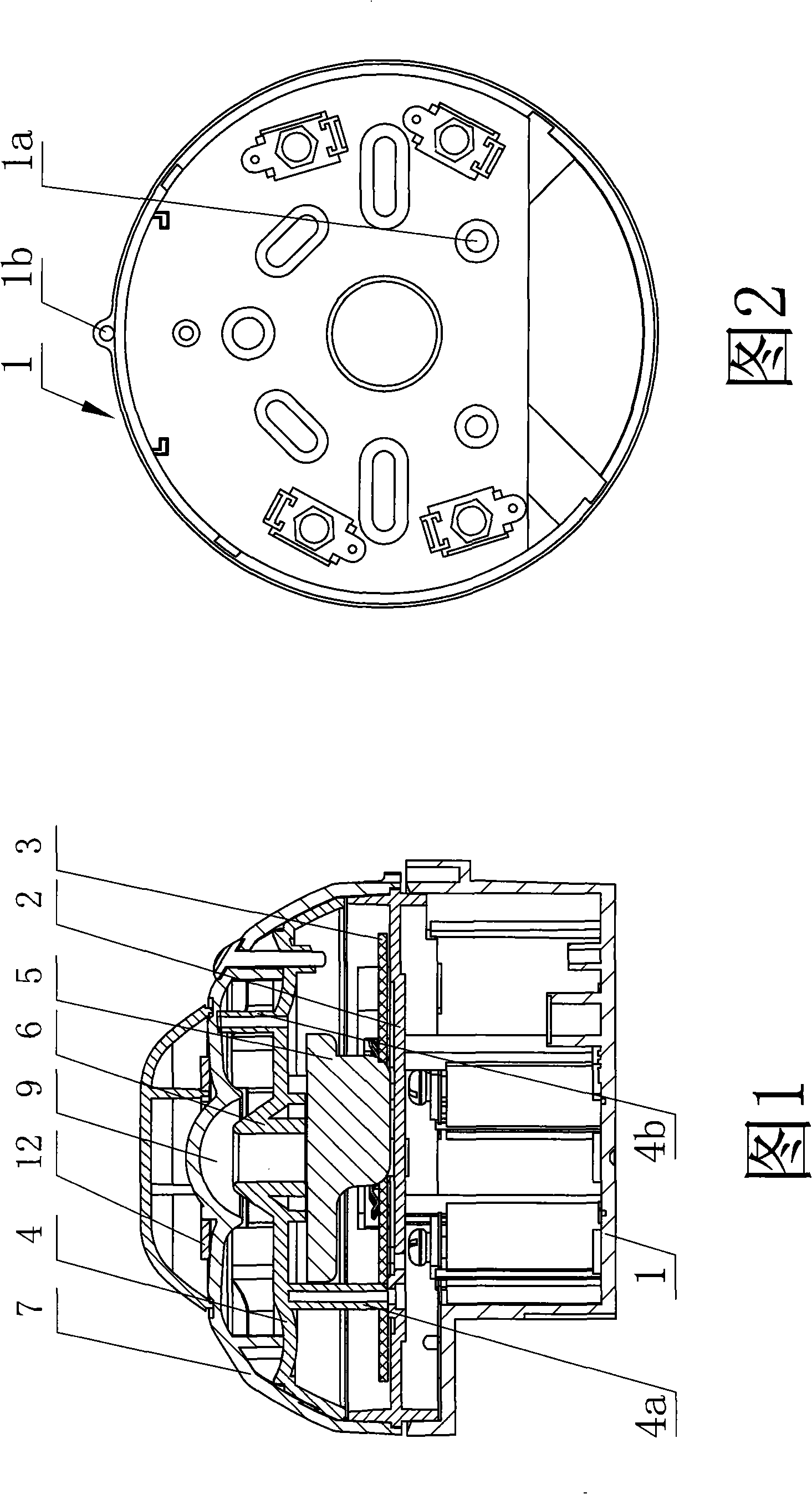
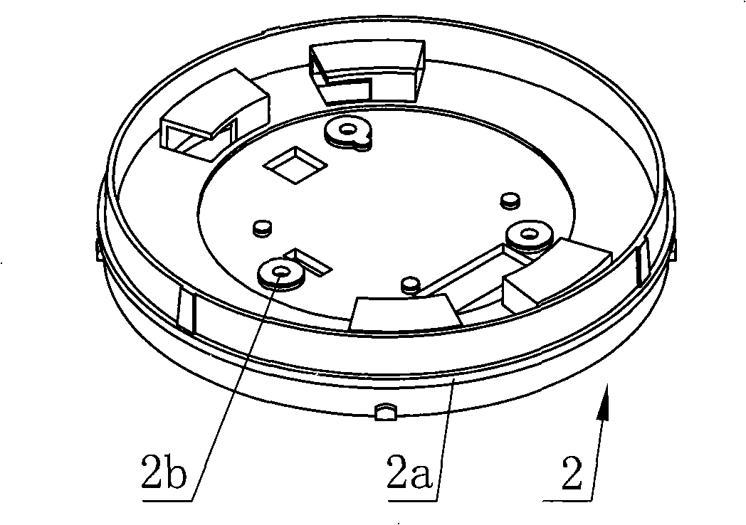
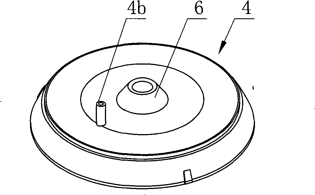
[0024] Referring to Figure 1, Figure 2, image 3 , Figure 4a , Figure 4b , Fig. 5a, Fig. 5b, the terminal alarm device of alarm system of the present invention, base 1 is cylindrical, and this base is the base with concave cavity, and the lower end of base 1 is provided with the mounting hole 1a that is used for assembling this base, and for wire Through the through hole, the upper end of the base 1 is circumferentially fixed with a control circuit support base 2 . The control circuit support seat 2 is cylindrical, and a boss 2a is provided on its outer peripheral wall, and three through holes 2b are evenly distributed on the control circuit support seat. The control circuit support seat 2 is fixed with a control circuit 3 for connecting the output end of the alarm signal detection device (not shown in the figure), the control circuit 3 receives the switch signal from the alarm signal detection device, and the control circuit 3 is started to work by the switch signal to so...


PUM


Abstract

The invention relates to an alarm system of a high-rise building. A terminal alarm device of the alarm system is as follows: a horn is arranged at the upper end of a supporting seat of a control circuit and outputs an alarm sound signal; a sounding device in the horn is electrically connected with the output end of the control circuit; a conical sound guide nozzle positioned above the sound part of the sounding device is arranged on the end surface of the horn; a superposition sound cavity is arranged at the upper end of the horn and covers the horn and the upper part of the supporting seat of the control circuit; the superposition sound cavity is fixedly connected with a seat through screws; the inner top wall of the superposition sound cavity is a concave arc-shaped surface; a sound guide cavity is arranged at the centre of the inner top wall of the superposition cavity; the conical sound guide nozzle of the horn and the sound guide cavity are in clearance fit; a space is arranged between the upper end surface of the horn and the inner top wall of the superposition sound cavity; and a plurality of sound extension openings are distributed on the side wall of the superposition cavity and penetrate the inner wall and the outer wall of the superposition cavity. The alarm system can strengthen the output alarm sound pressure and require less electric current.

Description

technical field [0001] The invention relates to an alarm device of an alarm system, in particular to a terminal alarm device of the alarm system. Background technique [0002] Today's terminal alarms have a wide variety of generators, including piezoelectric ones and loudspeakers. Piezoelectric generators have the advantages of high frequency, narrow frequency band, low current consumption, and stable sound at high frequencies; however, due to the small area of ​​the piezoelectric sheet and the characteristics of the silver layer, the sound pressure emitted is low, making it difficult to achieve high-pitched sound. The purpose of pressure alarm. The generator of the loudspeaker has a wide frequency band and can generate high sound pressure, but the area of ​​the diaphragm is relatively large, the required energy is high, and a large amount of current is consumed. In addition, the horn is also a kind of speaker. Although the horn has high power and high efficiency, it is bu...

Claims


Application Information

Patent Timeline
IPC IPC(8): G08B7/06G08B3/10G10K11/26
Inventor 徐金国
Owner BESTAR HLDG
Why Eureka
Try Eureka