
Control method for brushless DC motor

A brushless DC motor and control method technology, applied in the direction of single motor speed/torque control, torque ripple control, etc., can solve problems such as noise, amplitude difference, and waveform cycle inconsistency

Active Publication Date: 2008-12-17
GREE ELECTRIC APPLIANCES INC +1
View PDF0 Cites 16 Cited by
  • Summary
  • Abstract
  • Description
  • Claims
  • Application Information

AI Technical Summary

Problems solved by technology

[0004] Since the brushless DC motor generates back electromotive force during operation, when the voltage waveform provided by the inverter to the brushless DC motor is inconsistent with the voltage waveform of the opposite electromotive force, for example, there is a large phase between the voltage waveform provided by the inverter and the back electromotive voltage waveform Poor, or the waveform cycle is inconsistent, or there is a large difference in amplitude, which will make the torque generated by the part of the energized current in the brushless DC motor be opposite to the direction of the motor rotation, thus causing the brushless DC motor to vibrate and generate noise
However, the existing control of brushless DC motors does not consider whether the voltage waveform provided by the inverter to the brushless DC motor matches the voltage waveform of the back electromotive force, and often cannot effectively avoid the vibration of the brushless DC motor. At the same time, it cannot improve the DC Efficiency of brushless motors

Method used


Image

  • Control method for brushless DC motor
  • Control method for brushless DC motor
  • Control method for brushless DC motor

Examples


Embodiment Construction

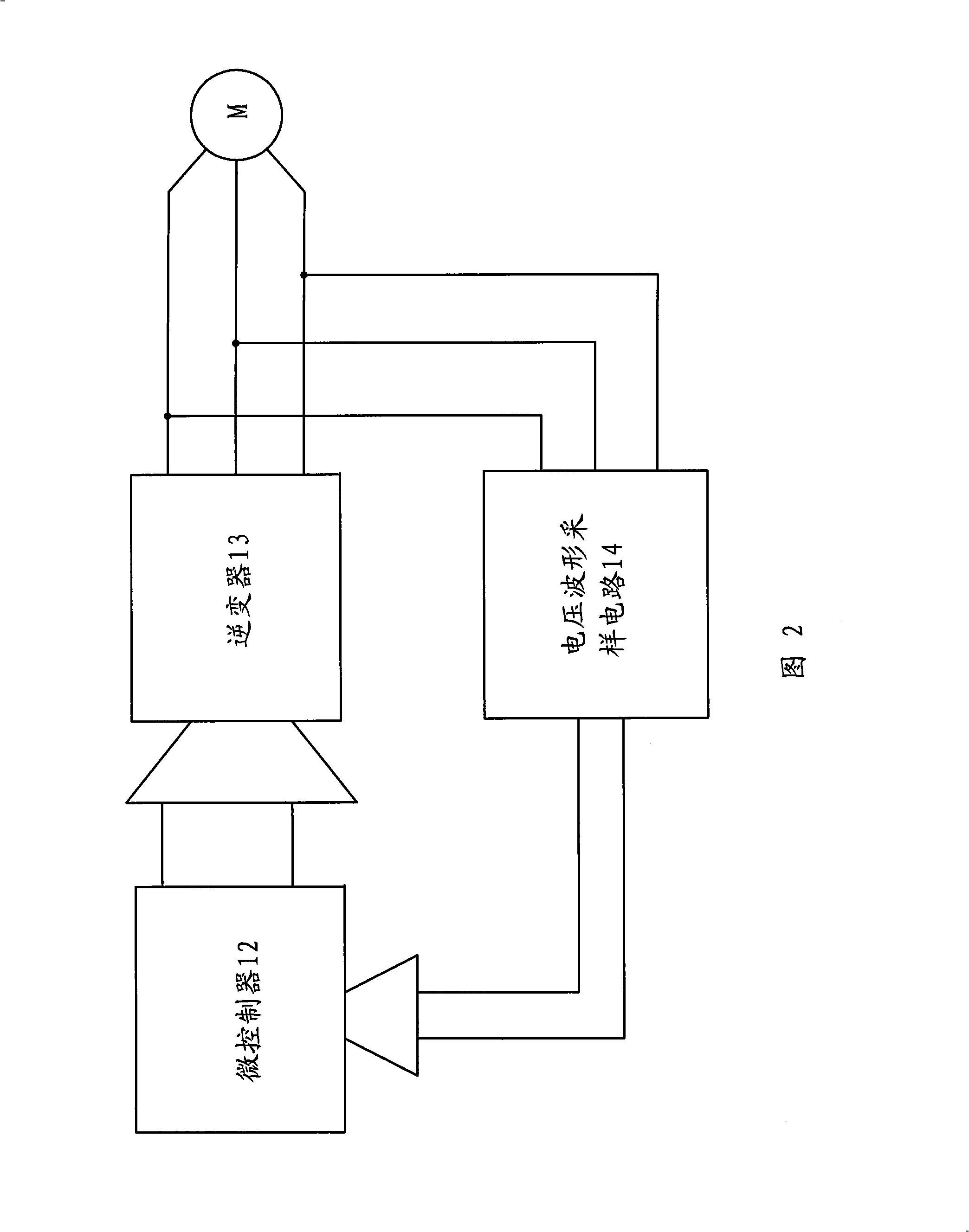
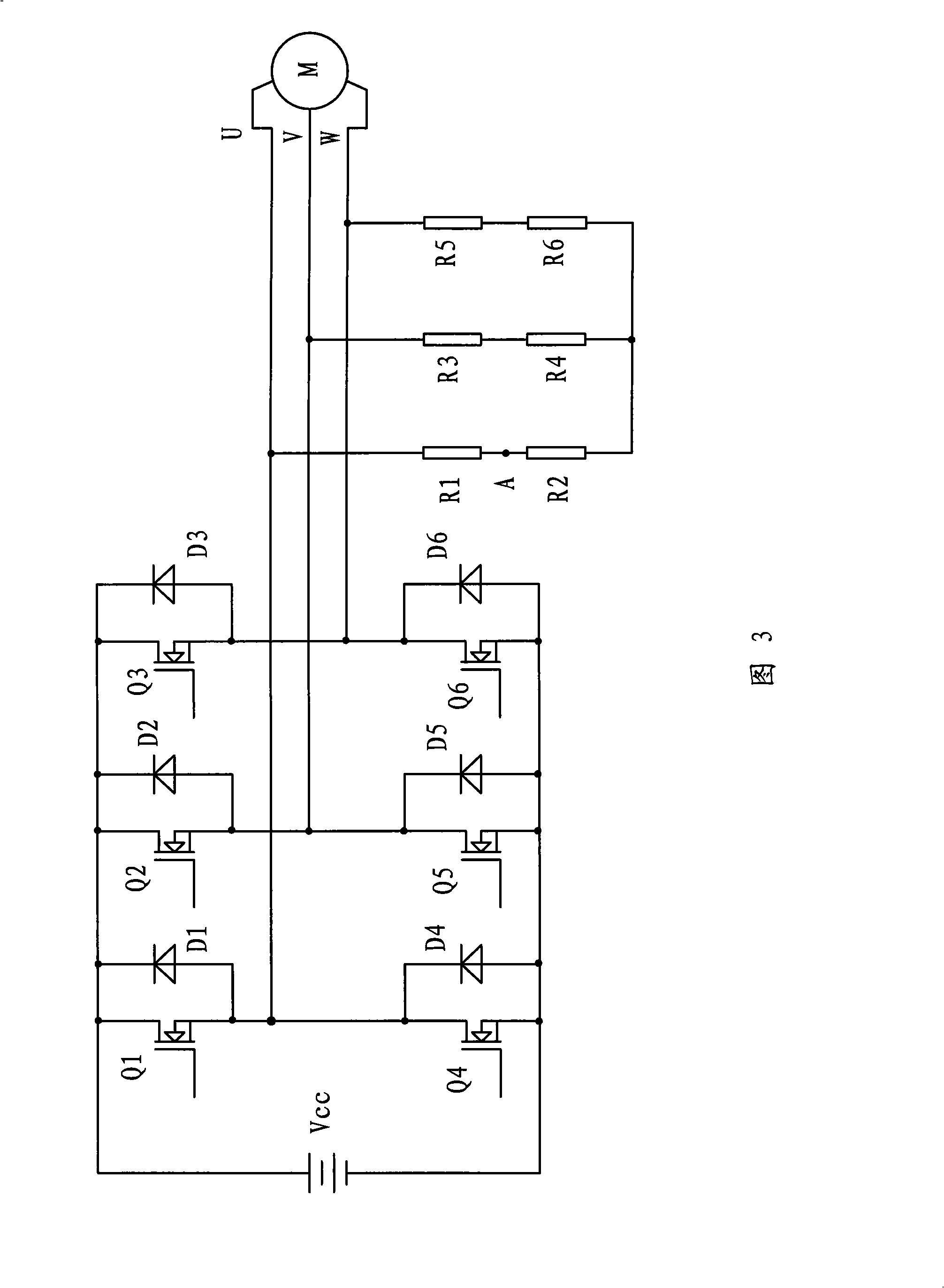
[0021] In the control method provided by the present invention, it is first necessary to establish the proportional relationship data between the rotational speed of the brushless DC motor and the voltage waveform data of the back electromotive force. Therefore, before the brushless DC motor is energized and operated, it is necessary to detect the back electromotive force of the brushless DC motor at a certain speed voltage waveform.

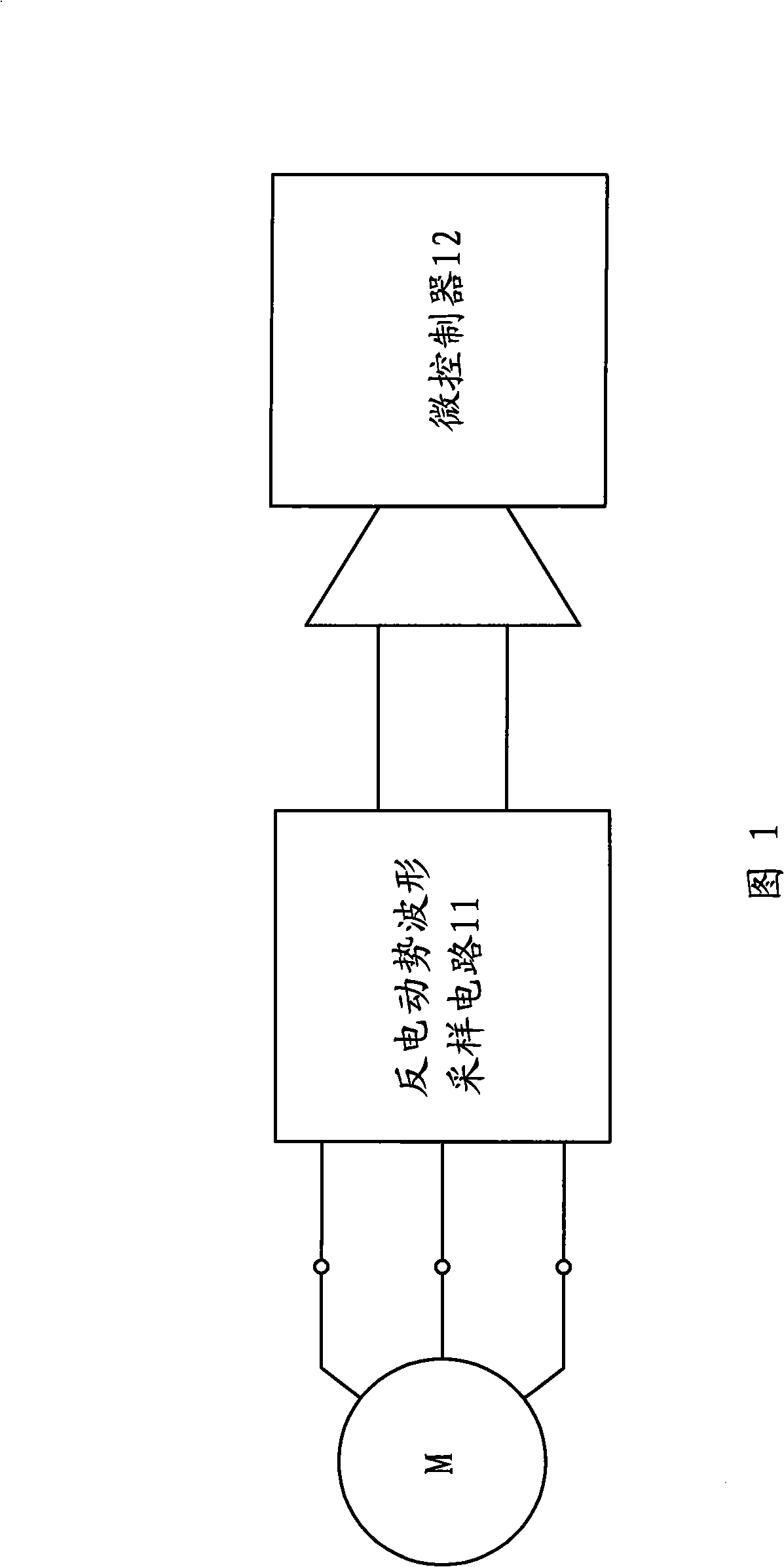
[0022] Referring to FIG. 1 , it is a schematic block diagram of the connection between the brushless DC motor, the counter electromotive force sampling circuit and the microcontroller in the embodiment of the present invention. It can be seen from Fig. 1 that the DC brushless motor M is connected to the back EMF waveform sampling circuit 11, and the back EMF waveform sampling circuit 11 collects the back EMF voltage waveform of the DC brushless motor M, including the period, phase, and amplitude of the back EMF voltage waveform, etc. data, and t...


PUM


Abstract

The invention provides a control method of a DC brushless machine, comprising a voltage waveform sampling circuit, an inverter and a microcontroller, wherein the method comprises: detecting the back electromotive force voltage waveform of the DC brushless machine in certain given rotating speed, storing the voltage waveform data in the microcontroller, building and storing the proportional relation data of the rotating speed and the back electromotive force by the microcontroller; after outputting the voltage from the inverter to the DC brushless machine, sampling the rotating speed in the DC brushless machine by the voltage waveform sampling circuit and the voltage waveform data outputted by the inverter, and transmitting to the microcontroller; computing the corresponding back electromotive force voltage waveform of the DC brushless machine and the error threshold range in the current rotating speed by the microcontroller, and judging whether the voltage waveform data input by the inverter exceeds the error threshold range, if true, the microcontroller emits the control signal to the inverter. The DC brushless machine of the invention has small vibration and advanced efficiency.

Description

technical field [0001] The invention relates to a control method of a motor, in particular to a control method of a DC brushless motor. Background technique [0002] Brushless DC motor is a kind of DC motor that cancels mechanical contact parts such as brushes and commutators. It uses microcontrollers instead of brushes and commutators. Therefore, the speed of brushless DC motors can be designed to be higher. , and can effectively avoid the noise generated by the brushes and commutator. [0003] The existing DC brushless motor adopts a 180° control method, and its control circuit includes a microcontroller and an inverter. The microcontroller outputs a control signal to the inverter, and the inverter sends a DC brushless Each phase of the brush motor provides a sine wave voltage to drive the brushless DC motor to work. [0004] Since the brushless DC motor generates back electromotive force during operation, when the voltage waveform provided by the inverter to the brushle...

Claims


Application Information

Patent Timeline
IPC IPC(8): H02P6/08H02P6/10
Inventor 王周叶
Owner GREE ELECTRIC APPLIANCES INC
Learn More