
Patsnap Eureka
For R&D, Patsnap Eureka makes reading and utilizing patents & technical documents easy.
Patsnap Eureka AIR
Designed for self-driven R&D workflows. Generate viable solutions, solve complex R&D challenges, empower your innovation with AI.

Patsnap Eureka Materials
Designed for material experts only. Revolutionize your material R&D, from search, analyze, to developing new materials.

TechResearch
Generate reliable direction feasibility study reports for your R&D in just a few steps.

TechSeek
Discover and master advanced knowledge NOW. Basics, ideas, possibilities, all at once.

TechMind
As an expert in R&D Theories, TechMind can generates customized viable solutions instantly.

TechRisk
Analyze your overall solution with one click, know your potential R&D risks in advance.

TechMonitor
Get weekly tech updates, stay abreast of the latest tech innovations and key insights.
RFID tag
A technology of RFID tags and power supply, applied in the field of RFID tags, can solve the problems of hard batteries, inflexibility, power supply that cannot be applied to RFID tags and non-contact IC cards, etc., and achieve the effect of being suitable for carrying
- Summary
- Abstract
- Description
- Claims
- Application Information
AI Technical Summary
Problems solved by technology
Method used
Image

Examples
example
[0119] (RFID tag production example 1)
[0120] Next, a fabrication example of the RFID tag according to the present embodiment will be described.
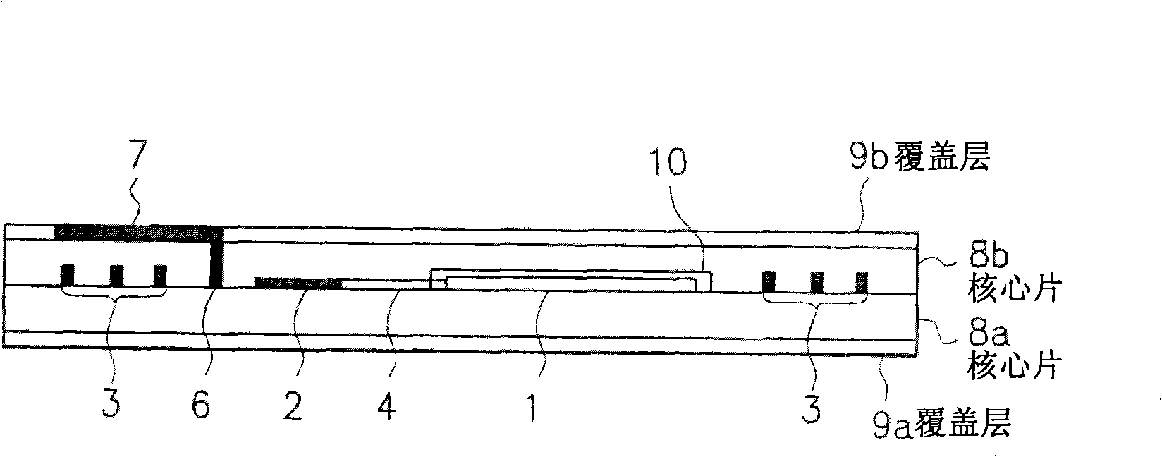
[0121] as figure 1 An IC card with an RFID tag of the cross-sectional structure shown in was obtained as follows.
[0122] First, prepare a 0.1mm thick cover layer 9b made of PVC; a 0.28mm thick PVC core sheet 8b in which the through-holes 6 for charging wiring and charging terminals 7 are arranged and include The cavity part 10 of 1; the 0.28mm thick PVC core sheet 8a, in which the organic radical battery 1, IC module 2, antenna 3, lead wire 4 and charging wiring 5 are arranged; and the 1.0mm thick PVC covering layer 9a. Thereafter, the cover layer 9a, the core sheet 8a, the core sheet 8b, and the cover layer 9a are laminated together in this order from the bottom, and are thermally crimped (120° C., pressure 2 kg / cm 2 ,2 minutes). As a result, fully made figure 1 IC card shown.
example 2
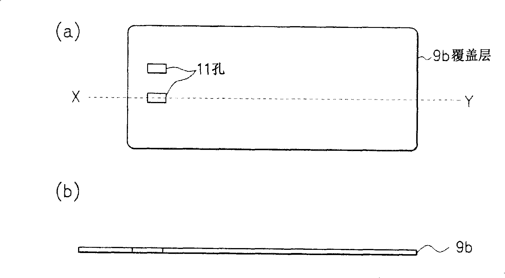
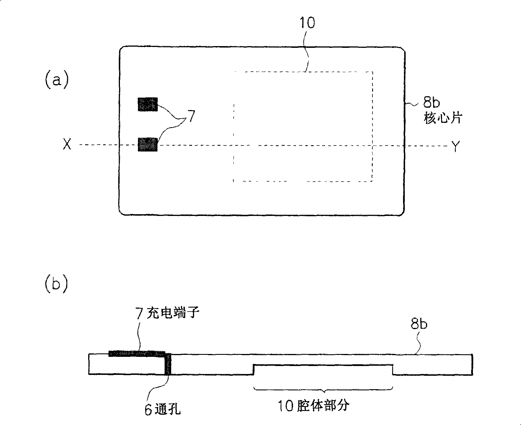
[0124] as Figure 7 IC cards of RFID tags shown in (a) and 7(b) were obtained as follows.
[0125] Prepare a 0.1mm thick PVC cover layer 9b, which includes an opening portion through which the organic radical battery 1 and small protrusions 11 can pass; a 0.28mm thick PVC core sheet 8b, in which wiring for charging and charging The through hole 6 of the terminal 7, and includes a space portion for accommodating the organic radical battery 1; a 0.28mm thick PVC core sheet 8a, in which the IC module 2, the antenna 3, the lead wire 4 and the charging wiring 5 are arranged; and 1.0mm Thick PVC cover 9a. Thereafter, the cover layer 9a, the core sheet 8a, the core sheet 8b, and the cover layer 9a are laminated together in this order from the bottom, and are thermally crimped (120° C., pressure 2 kg / cm 2 , 2 minutes) to shape into a card. A sealing layer 100 (length 40mm×width 40mm×thickness 0.4mm) comprising a thin-film organic radical battery 1 is fixed to the card so that the b...
PUM
| Property | Measurement | Unit |
|---|---|---|
| Thickness | aaaaa | aaaaa |
Abstract
Description
Claims
Application Information
 - R&D Engineer
- R&D Manager
- IP Professional
- Industry Leading Data Capabilities
- Powerful AI technology
- Patent DNA Extraction
Browse by: Latest US Patents, China's latest patents, Technical Efficacy Thesaurus, Application Domain, Technology Topic, Popular Technical Reports.
© 2024 PatSnap. All rights reserved.Legal|Privacy policy|Modern Slavery Act Transparency Statement|Sitemap|About US| Contact US: help@patsnap.com