

Mechanism of plastic rubber mold and compressed-air linked ejection mechanism
A technology of compressed air and ejection mechanism, applied in the field of plastic injection molding, which can solve problems such as uneven blowing force, small blowing force, and large blowing force, and achieve the effects of reducing friction, blowing air evenly, and prolonging the service life
- Summary
- Abstract
- Description
- Claims
- Application Information
AI Technical Summary
Problems solved by technology
Method used
Image

Examples
Embodiment Construction
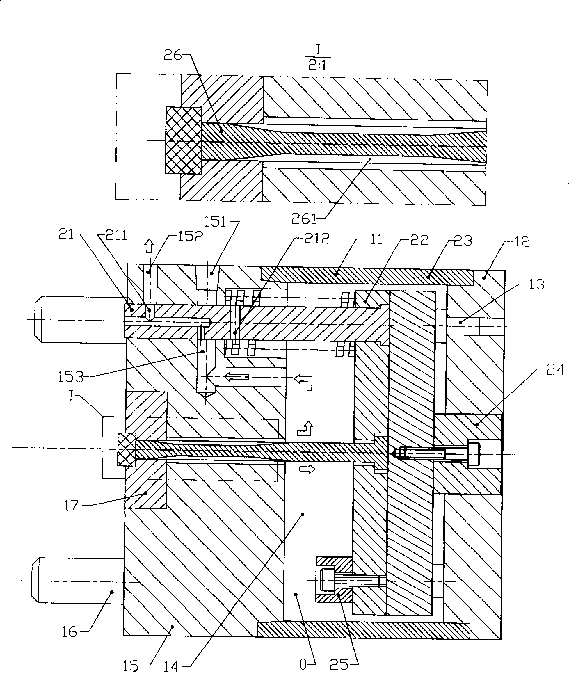
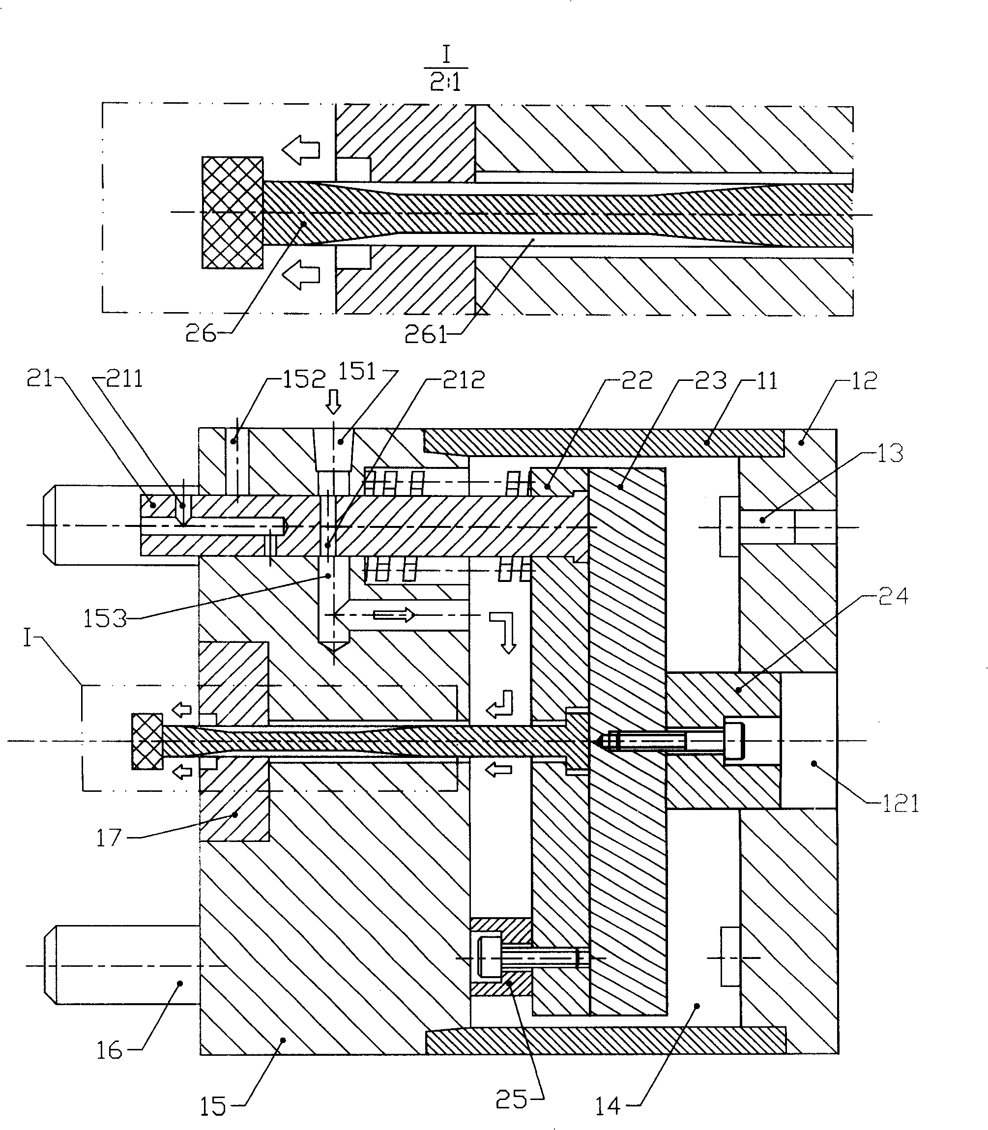
[0015] The preferred embodiment of the present invention is described. See figure 1 and figure 2 . A mold mechanism that adds compressed air to the original ejection mechanism for linkage ejection.
[0016] The movable mold side part of this mechanism includes a fixed component and an ejector component. The fixed assembly includes the following parts: sealing plate (11), bottom plate (12), limit nail (13), die foot (14), movable template (15), guide post (16), molding parts (17); The assembly includes the following parts: reset lever (21), upper thimble plate (22), lower thimble plate (23), jacking block (24), limit block (25), thimble (26).
[0017] In the fixed assembly, a sealing plate (11) is respectively provided at both ends of the mold foot (14), so that the movable formwork (15), sealing plate (11), mold foot (14), and bottom plate (12) have just formed A space to accommodate ejection components. An air inlet (151), an exhaust port (152), and a gas channel (153)...
PUM
 Abstract
Description
Claims
Application Information