Crank arm assembly and related crank arm and element for transmitting torque from the crank arm to a bicycle chain

A crank arm, bicycle technology, applied in crank structure, vehicle components, transportation and packaging, etc., can solve problems such as broken crank arms, and achieve the effects of reducing stress concentration, small size, and high-efficiency motion transmission

Inactive Publication Date: 2008-12-24
CAMPAGNOLO SRL
View PDF7 Cites 22 Cited by
  • Summary
  • Abstract
  • Description
  • Claims
  • Application Information

AI Technical Summary

Problems solved by technology

This leads to high stress concentrations at the joint between the crank arm and the adapter, with a

Method used


Image

  • Crank arm assembly and related crank arm and element for transmitting torque from the crank arm to a bicycle chain
  • Crank arm assembly and related crank arm and element for transmitting torque from the crank arm to a bicycle chain
  • Crank arm assembly and related crank arm and element for transmitting torque from the crank arm to a bicycle chain

Examples


Embodiment Construction

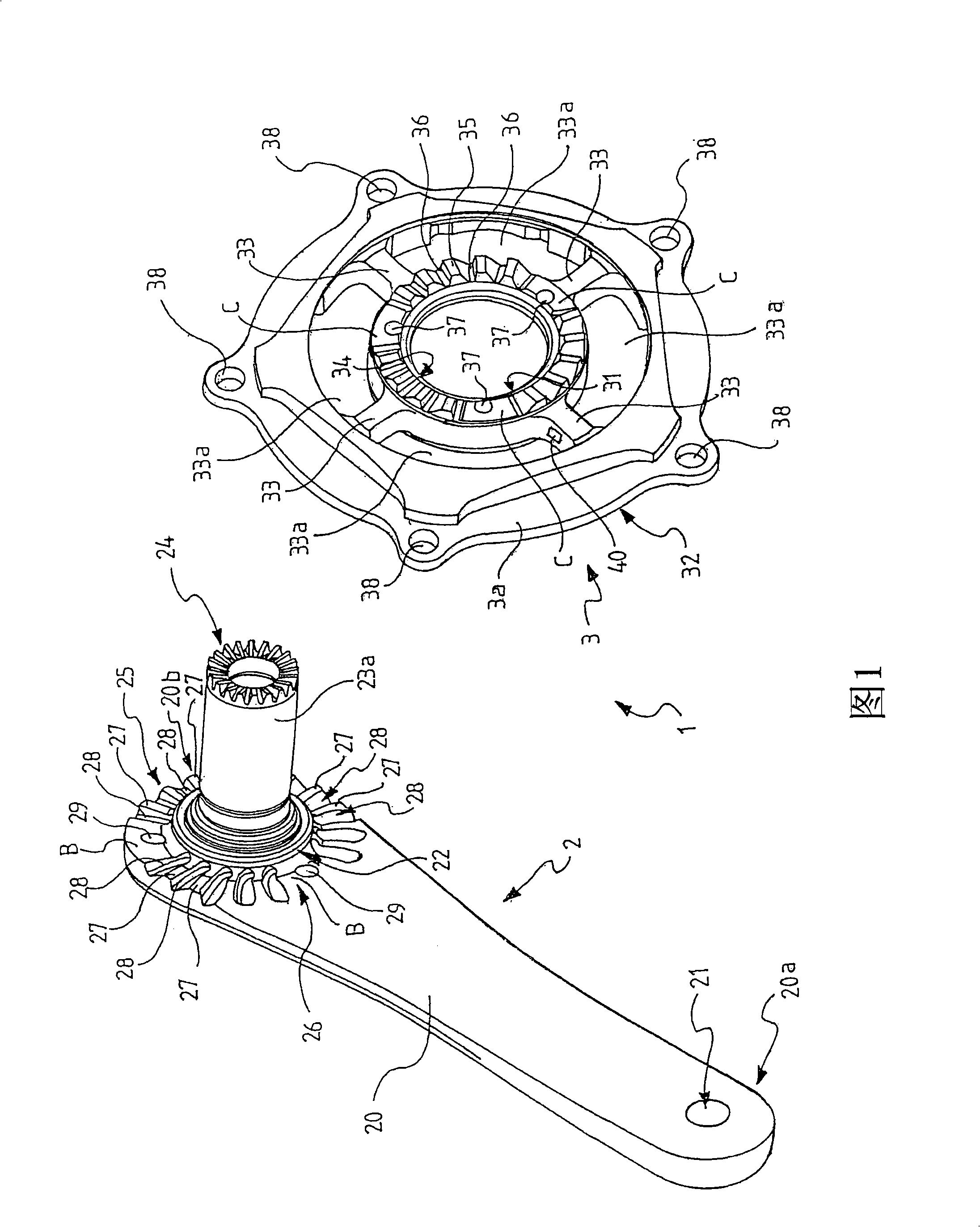
[0093] In the accompanying drawings, reference numeral 1 denotes a crank arm assembly according to the present invention. In particular, the crank arm assembly 1 is a right crank arm assembly and is intended for use in the chassis assembly of a bicycle, preferably a racing bicycle, to transmit motion from the crank arm to the bicycle chain through the crown of the bicycle chainring.

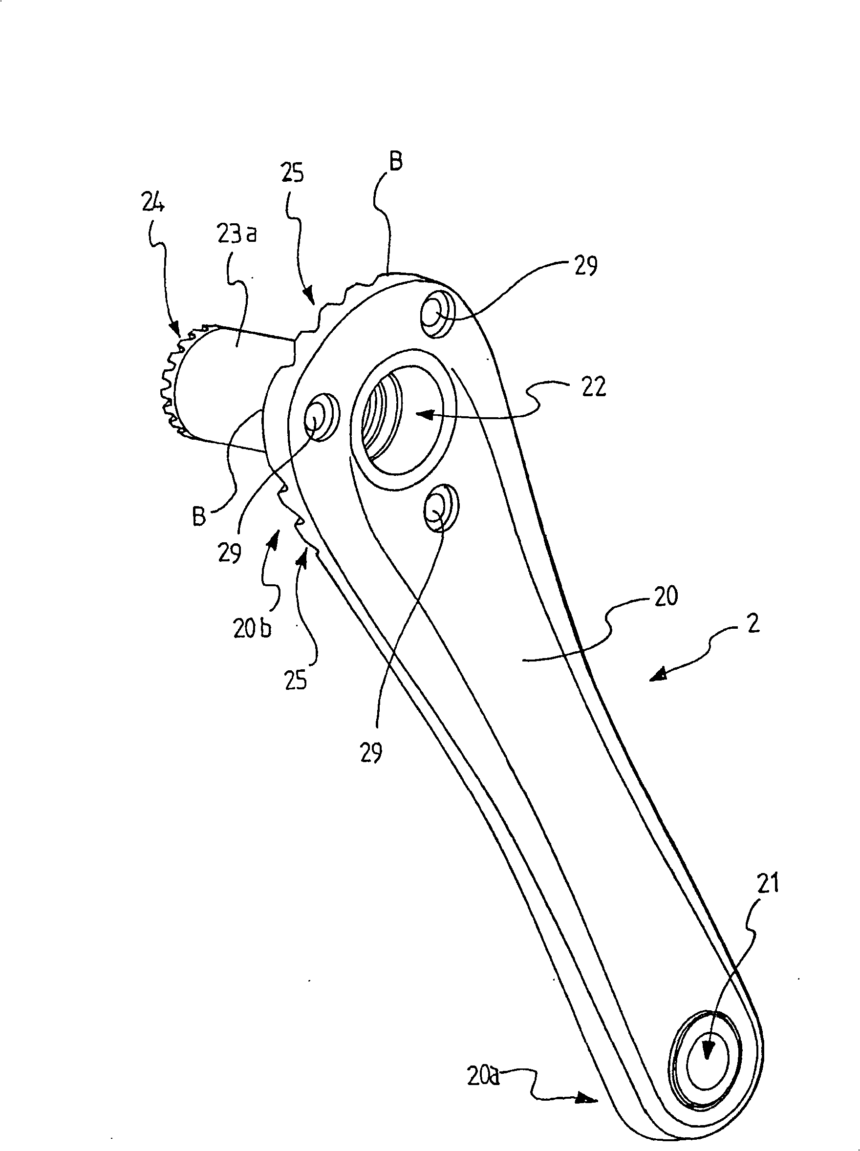
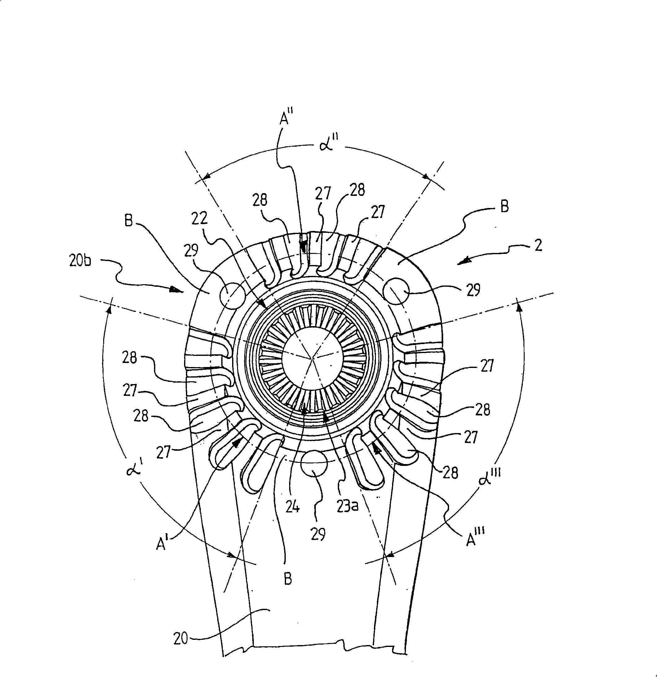
[0094] Figure 1 shows a first embodiment of the crank arm assembly of the present invention. The crank arm of this crank arm assembly is in the figure 2 -4 is shown in detail, while the Figure 5 A chassis assembly using the crank arm assembly of FIG. 1 is shown.

[0095] 1-5 above, crank arm assembly 1 includes: crank arm 2, suitable for use as the right crank arm; and adapter 3a, suitable for use with crank arm 2 and crown ( Figure 5 Indicated with 200) coupling, thereby allowing torque to be transmitted from the crank arm 2 to the rear wheel of the bicycle (not shown). This movement is impa...


PUM


Abstract

A crank arm assembly (1) for a bicycle, comprising a crank arm (2) and an element (3,3a) for transferring torque from the crank arm (2) to a bicycle chain. The crank arm (2) and the element (3,3a) for transferring torque respectively comprise first (25) and second (34) front coupling means provided with respective matching profiles adapted to be coupled together to transfer torque from the crank arm (2) to the element (3,3a) for transferring torque. In particular, the first and second means for transferring torque comprise respective front toothings, preferably Hirth toothings. The crank arm assembly (1) is very light and is stronger in structure than crank arm assembly known.

Description

technical field [0001] The present invention relates to a crank arm assembly for a bicycle. The invention also relates to a crank arm for this assembly, and elements for transmitting torque from said crank arm to a bicycle chain. Background technique [0002] Throughout this specification and the appended claims, the term "crank arm assembly" is used to denote an assembly comprising a crank arm and elements adapted to be connected to the crank arm to allow the transfer of motion to the rear wheel of a bicycle, the motion being directed by the rider It is applied to the crank arm by the pedals and transmitted to the rear wheel through the chain coupled to the crown of the bicycle chainring. [0003] It is known that, in right crank arm assemblies, the crown is directly coupled with the right crank arm. See eg EP1 354 792 and EP 0 414 907 . [0004] In this assembly, the right crank arm is manufactured in a star shape and includes a plurality of coupling arms extending in c...

Claims


Application Information

Patent Timeline
IPC IPC(8): B62M3/00B62M9/00
CPCB62M3/00B62M3/003B62M9/10Y10T74/2164
Inventor 马里奥·梅焦兰
Owner CAMPAGNOLO SRL
Why Eureka
Try Eureka