Trisection ellipse spiral traverse baffle shell type heat exchanger

A technology of shell-and-tube heat exchangers and spiral baffles, which can be applied to the types of heat exchangers, indirect heat exchangers, lighting and heating equipment, etc., and can solve problems that affect the popularization and application of baffles and the difficulty of marking and positioning , to achieve the effects of easy positioning, scribing and processing, improved strength conditions, and reduced support spacing

Inactive Publication Date: 2008-12-24
SOUTHEAST UNIV
View PDF0 Cites 10 Cited by
  • Summary
  • Abstract
  • Description
  • Claims
  • Application Information

AI Technical Summary

Problems solved by technology

Since a large number of shell-and-tube heat exchangers use the most compact regular triangular arrangement of tube bundles, this makes it difficult to mark and position inclined tube holes on 1 / 4 elliptical / fan-shaped baffles. Affected the popular application of this type of baffle

Method used


Image

  • Trisection ellipse spiral traverse baffle shell type heat exchanger
  • Trisection ellipse spiral traverse baffle shell type heat exchanger
  • Trisection ellipse spiral traverse baffle shell type heat exchanger

Examples


Embodiment 1

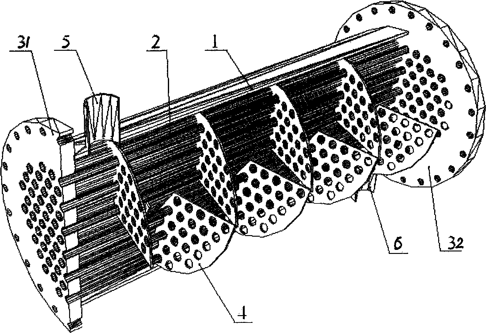
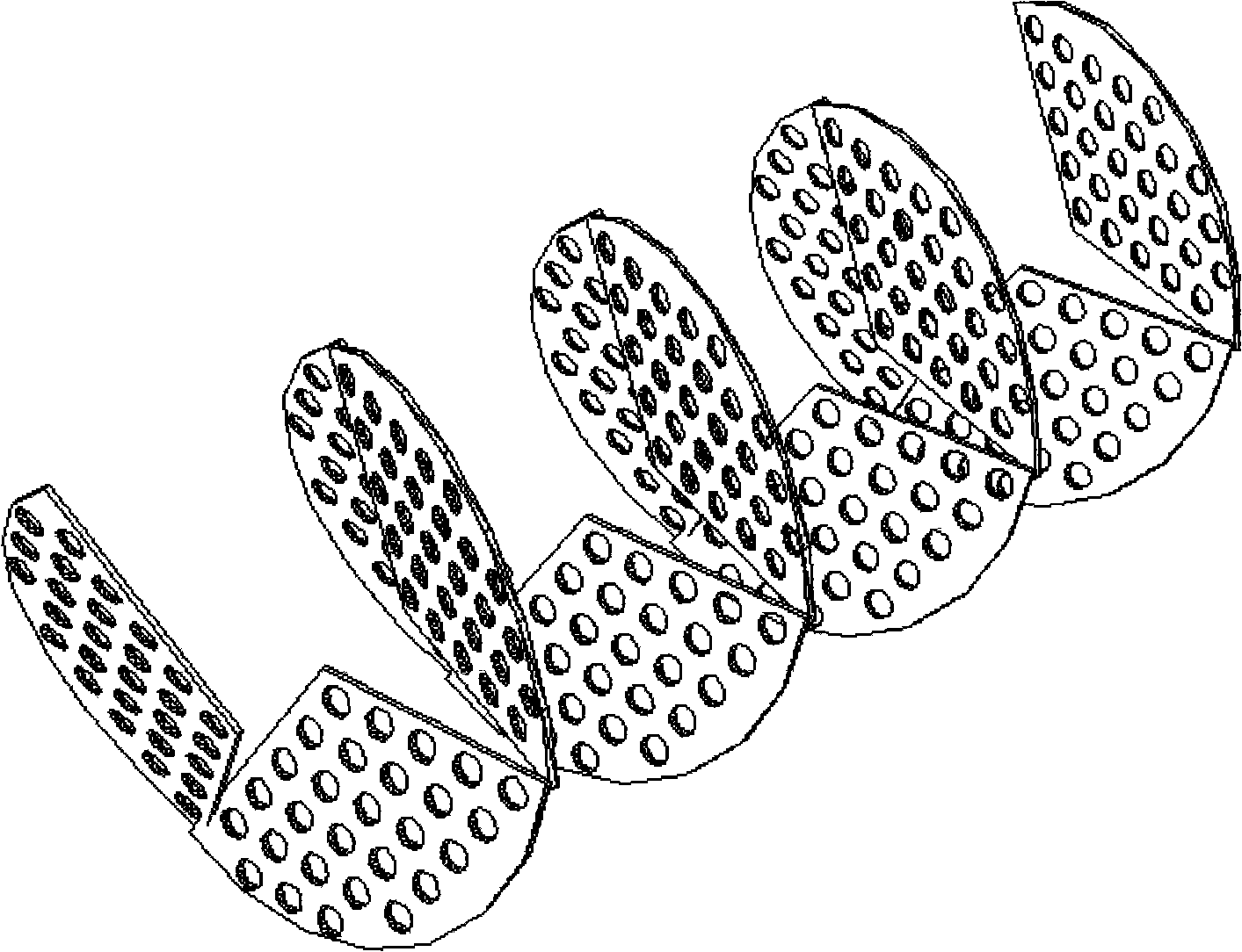
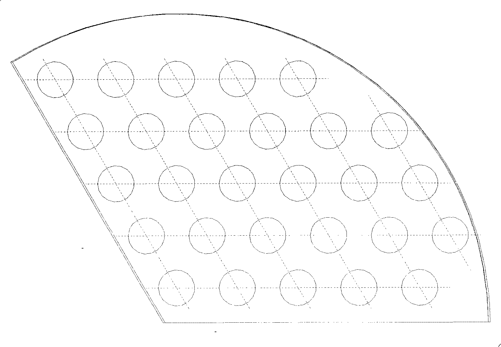
[0021] Embodiment 1: as Figure 1-5 As shown, the present invention includes a cylindrical shell 1, a tube bundle 2, a left tube plate 31, a right tube plate 32, a fluid inlet joint 5, a fluid outlet joint 6, and the left tube plate 31 and the right tube plate 32 are concentrically arranged and welded on At both ends of the cylindrical shell 1, each tube of the tube bundle 2 penetrates through the left tube plate 31, and then protrudes from the right tube plate 32, and the end of each tube is welded or expanded with the tube plate 3 The fluid inlet connecting pipe 5 and the fluid outlet connecting pipe 6 are based on the principle of facilitating the uniform distribution of the fluid after entering the housing and the convenience of collecting the fluid. Each baffle 4 is obliquely arranged in the cylindrical housing 1, and the projection of each baffle 4 occupies about one-third of the inner section circle of the cylindrical housing 1; each baffle 4 is composed of An elliptic...

Embodiment 2

[0025] Such as Figure 6 As shown, the baffles 4 of the present invention may not be strictly divided into thirds, but are separated by the natural intervals of the tube bundles according to the principle of thirds, and the straight sides of the baffles 4 can be used when necessary. Stepped sides to accommodate natural spacing of tube bundles. For example, due to the requirement of multi-tube arrangement, there are gaps between some tube bundles, so there is a situation that the natural intervals of tube bundles distributed in two areas cannot be connected in a straight line. At this time, you can follow Figure 6 As shown, it is solved by the method of step folded line edge.

Embodiment 3

[0027] Such as Figure 7 As shown, the structure of this embodiment is suitable for a U-shaped tube bundle shell-and-tube heat exchanger with regular triangle arrangement of tubes. The plate is divided into 2 120° divisions and 2 60° divisions, and they are arranged centrally symmetrically; or further simplified into 2 180° divisions.


PUM


Abstract

The invention discloses a shell-and-tube heat exchanger that has spiral traverse baffles with the projection of one third of an ellipse, and relates to the shell-and-tube heat exchangers with spiral traverse baffles, in particular to the technical field of the shell-and-tube heat exchangers with tubes that are arranged in an upright triangle. Tube plates of the shell and tube heat exchanger are concentrically arranged and welded at the two ends of a cylindrical shell, each traverse baffle is obliquely arranged inside the cylindrical shell, and the projection of each traverse baffle occupies about one third of the cross-section circle of the cylindrical shell, each traverse baffle consists of one curved ellipse edge and two straight edges, wherein, one edge that is coincident with or parallel to the major semi-axis of a tangential ellipse of the traverse baffle is taken as a reference edge, which is parallel to the connecting line of tube orifice centers of the tubes that are arranged in the upright triangle and contained in the traverse baffle, the other edge is an oblique edge, the reference edge of one traverse baffle and the oblique edge of the other adjacent traverse baffle are connected end to end, and tube orifices on each traverse baffle are arranged correspondingly to tube orifices on the tube plate. The shell-and-tube heat exchanger with the spiral traverse baffles achieves the aim of high heat exchange efficiency and lowered loss of resistance force and is applicable to the upright triangle arrangement of the tubes.

Description

technical field [0001] The invention relates to a shell-and-tube heat exchanger with spiral baffles, in particular to the technical field of a shell-and-tube heat exchanger with pipes arranged in an equilateral triangle. Background technique [0002] The shell and tube heat exchanger is still the mainstream type of heat exchange equipment because of its simple structure and high pressure. Although the commonly used bow-shaped baffles are simple to manufacture, they have disadvantages such as flow dead zone, large flow resistance, and large tube bundle support span at the gap, which is easy to induce vibration damage, etc., thus giving birth to many new tube bundle support solutions. Spiral baffles are one of them. Theoretically, the spiral baffle is a curved surface, which is difficult to manufacture. There are already 1 / 4 elliptical / fan-shaped spiral baffles in foreign countries. The connection can form the shell-side spiral channel. Since a large number of shell-and-tub...

Claims


Application Information

Patent Timeline
Patent Type & Authority Applications(China)
IPC IPC(8): F28D7/10
Inventor 陈亚平
Owner SOUTHEAST UNIV
Why Eureka
Try Eureka