Reed for camera lens drive mechanism

A lens drive and camera technology, applied in installation, optics, instruments, etc., can solve problems such as easy deformation of spring wire, deviation of concentricity and optical axis degree of lens support body, displacement deviation of optical axis direction, etc., to improve the ability of anti-deformation , avoid rotation offset, and improve impact resistance

Inactive Publication Date: 2008-12-24
NINGBO JCT ELECTRONICS
View PDF1 Cites 6 Cited by
  • Summary
  • Abstract
  • Description
  • Claims
  • Application Information

AI Technical Summary

Problems solved by technology

[0005] Yet one of its weak points is that the annular outer profile and the annular inner profile in the above-mentioned front and rear reeds are only connected by a plurality of substantially linear spring wires, therefore, the whole front and rear reeds Rigidity, impact resistance and deformation resistance are relatively poor. When such front and rear reeds are stressed, the spring wires on them are easily deformed, which will cause the lens in the lens driving structure using the reed to lose light. Deviation occurs when the axis is displaced, which affects the imaging quality of the camera
[0006] Secondly, the shape of the front and rear reeds is annular and dislocated in the same direction. Therefore, when the reeds are deformed in the forward and backward displacement, a rotational force in the same direction will be generated at the same time, which will easily cause the lens support to rotate and deviate.
[0007] Again, the connection and positioning device between the front reed and the rear reed and the lens support has a lot of procedures, and the positioning of the front reed and the rear reed depends on the position of the external frame and the base. The inner edge and the outer edge of the front reed and the rear reed are coordinated and positioned. Once there is a problem with the tolerance of one of the above-mentioned components, it is very easy to cause a large concentricity and optical axis deviation of the supported lens support. degrade image quality

Method used


Image

  • Reed for camera lens drive mechanism
  • Reed for camera lens drive mechanism
  • Reed for camera lens drive mechanism

Examples


Embodiment Construction

[0023] The present invention will be further described in detail below in conjunction with the accompanying drawings and embodiments.

[0024] Such as Figure 1~4 Shown is a preferred embodiment of the present invention.

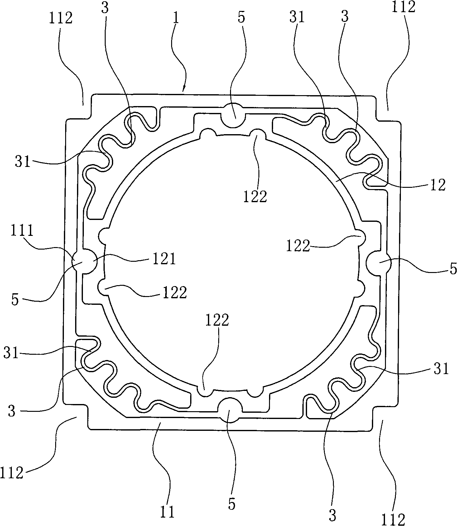
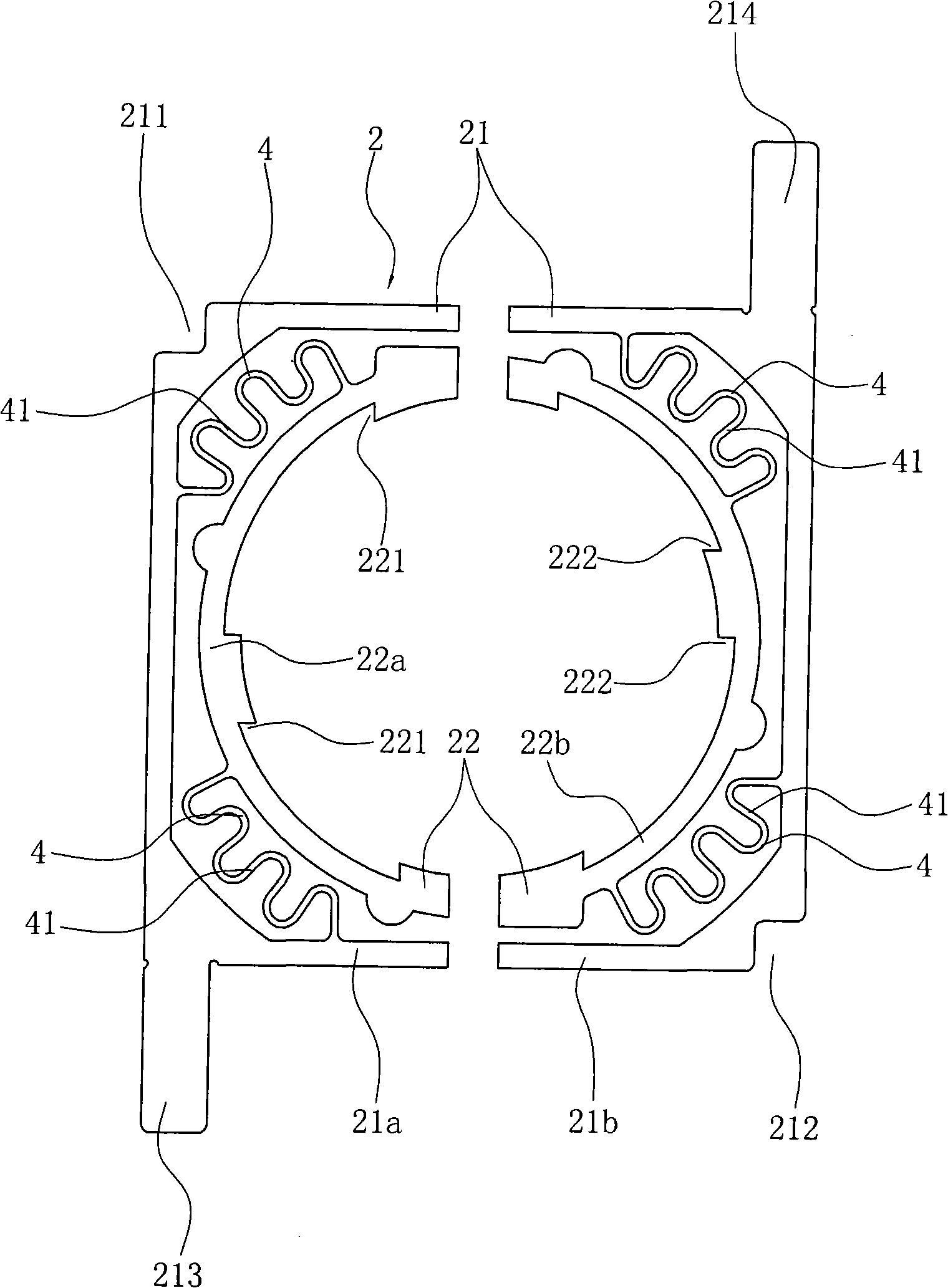
[0025] A reed for a camera lens drive mechanism. Generally, there are two types of reeds in a camera lens drive mechanism, namely the front reed 1 and the rear reed 2. The front and rear reeds 1 and 2 are integrally formed into a thin sheet .

[0026] Now set forth the concrete structure of front reed 1 and rear reed 2.

[0027] The front reed 1 is composed of an annular outer profile 11 and an annular inner profile 12, and the outer profile 11 and the inner profile 12 are both integral.

[0028] Wherein, the outer frame 11 is in a square shape, and each of the four outer corners of the outer frame 11 is provided with an L-shaped glue joint opening 112 facing outward.

[0029] The inner profile 12 is circular, and the inner profile 12 is located in the o...


PUM


Abstract

The invention relates to reeds for a camera lens drive mechanism, the reeds (1, 2) are shaped like flakes as a whole and consist of annular outer profiles (11, 21) and annular inner profiles which are positioned in the outer profiles (11, 21), spacing intervals are provided between the inner walls of the outer profiles and the outer walls of the inner profiles, the outer profiles and the inner profiles are connected by at least two connection reed threads (3, 4) which are arranged at intervals, and the connection reed threads (3, 4) are coiled and arranged along a circumferential continuous shape of U. The outer profiles are square or rectangular, the inner profiles are circular, and the connection reed threads are arranged at the side angels in the outer profiles. The connection reed threads can improve the anti-deformation capacity through the U-shaped coiling role, and the connection reed threads further have good elastic effect and can effectively improve overall stiffness and impact resistance performance, thereby ensuring the good imaging quality of the lens drive mechanism which uses the reeds.

Description

technical field [0001] The invention belongs to the field of camera lens driving devices; in particular, it relates to a reed used for a camera lens driving mechanism which maintains its motion balance and stability during the lens driving process. The invention is mainly used in the lens driving mechanism of the miniature camera with automatic focusing function, and is matched with miniaturized and high-quality sensors, and is especially suitable for supporting applications in mobile phones, computers, automobiles and robots. Background technique [0002] The structure of the similar lens driving device adopted in existing miniature cameras at home and abroad is relatively common, such as the scheme disclosed in "Lens Driving Device" in Chinese Patent No. 200410017724.3, which includes a cylindrical yoke ring installed on the base , a magnet and a coil are arranged in the yoke ring, and a lens with a lens support is arranged on the inner peripheral side of the coil; the mag...

Claims


Application Information

Patent Timeline
Patent Type & Authority Applications(China)
IPC IPC(8): G02B7/04G03B30/00
Inventor 金仁召
Owner NINGBO JCT ELECTRONICS
Why Eureka
Try Eureka