Current-differential relay device

A current differential and relay technology, applied to electrical components, circuit devices, emergency protection circuit devices, etc., to achieve the effect of improving the analysis function

Inactive Publication Date: 2008-12-24
MITSUBISHI ELECTRIC CORP
View PDF1 Cites 2 Cited by
  • Summary
  • Abstract
  • Description
  • Claims
  • Application Information

AI Technical Summary

Problems solved by technology

[0005] In this way, the conventional current differential relays have the problem of obtaining the adjustment value of the other device, the state of the relay element, and the input and output signals of the device for the purpose of analyzing the operation of the relay. It takes a lot of time and investment in equipment to analyze data and take appropriate measures in places where the other party's equipment is tens of kilometers away from the own equipment, or if a special monitoring and control system is installed in advance.

Method used


Image

  • Current-differential relay device
  • Current-differential relay device
  • Current-differential relay device

Examples


Embodiment Construction

[0047] Next, embodiments of the current differential relay of the present invention will be described in detail with reference to the drawings. In addition, this invention is not limited to this embodiment.

[0048] Embodiment 1

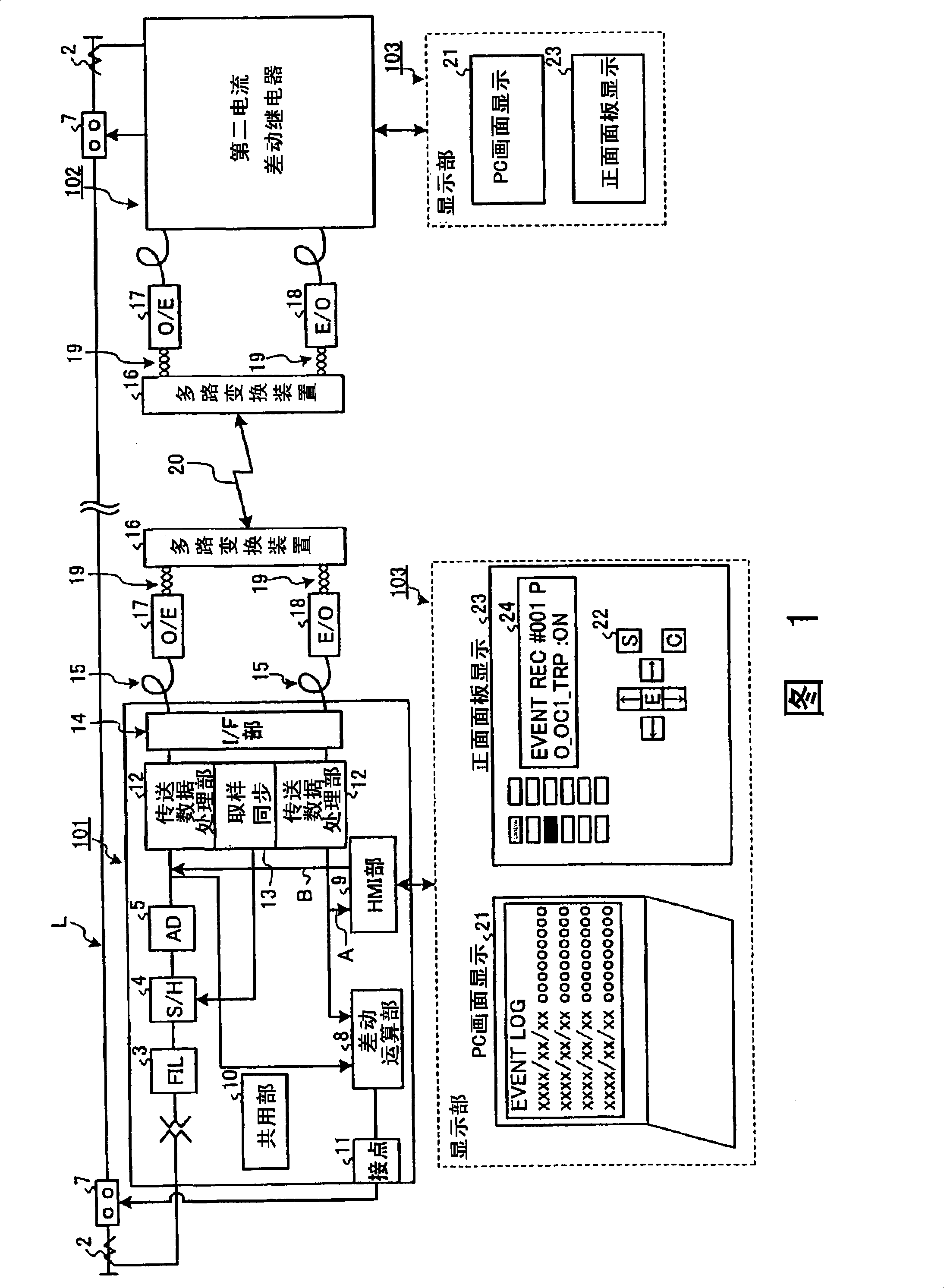
[0049] Fig. 1 is a system configuration diagram of Embodiment 1 of a current differential relay of the present invention. In Fig. 1, two current differential relays are set respectively at both ends of the protection interval of the transmission line L, and connected to the transmission line L. Among these current differential relays, the first current differential relay 101 is connected to one end side of the protection section of the transmission line L, and the output terminal of the first current differential relay 101 is connected to the circuit breaker 7 provided on the transmission line through the contact point 1. superior. The second current differential relay 102 connected to the other end side of the protected section of the transmissio...


PUM


Abstract

The present invention provides a current-differential relay capable of obtaining various data of other party current-differential relay. The relay device, installed at one end of a power line (L) within a protected zone, includes a processor performing a transmitting process that transmits first sampling current data of the power line (L) at the one end to another relay device installed at the other end, through a 2048-kbps transmission line, and a receiving process that receives second sampling current data of the power line (L) at the other end from the another relay device through the transmission line. The processor transmits the sampling current data in a transmission frame, and transmits, using an unused field not for the sampling current data in the transmission frame, display-related data output from the human-machine interface.

Description

technical field [0001] The present invention relates to a current differential relay. The current differential relay is arranged at each end of the protection zone of the power transmission line, and sends the sampled current data of the current flowing through the power transmission line at its own end to the opposite end through a specified transmission route, and at the same time Receive the sampled current data from the other end flowing through the transmission line through the transmission line, calculate the difference current between the sampled current data detected by the own end and the sampled current data transmitted from the other end, and detect accidents in the protection zone. technical background [0002] In the current differential relay configured in this way, the data transmission between the current differential relays samples the current data of each phase of the own device and the other device at a period of 30 degrees, and transmits and receives the d...

Claims


Application Information

Patent Timeline
Patent Type & Authority Applications(China)
IPC IPC(8): H02H3/28
Inventor 反町孝史服部孝
Owner MITSUBISHI ELECTRIC CORP
Why Eureka
Try Eureka