
Vane-type demister

A louver plate and thin plate technology, which is applied in the direction of chemical instruments and methods, separation methods, and dispersed particle separation, can solve the problems of increasing manufacturing complexity and achieve the effect of avoiding pressure drop

Active Publication Date: 2008-12-24
UOP LLC
View PDF4 Cites 13 Cited by
  • Summary
  • Abstract
  • Description
  • Claims
  • Application Information

AI Technical Summary

Problems solved by technology

But welding, bolting, or other joining methods for the louvers add manufacturing complexity

Method used


Image

  • Vane-type demister
  • Vane-type demister
  • Vane-type demister

Examples


Embodiment Construction

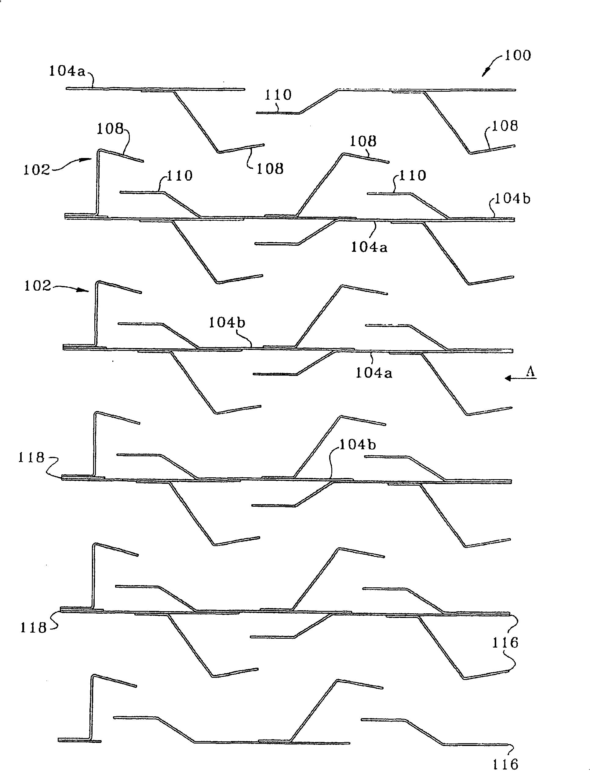
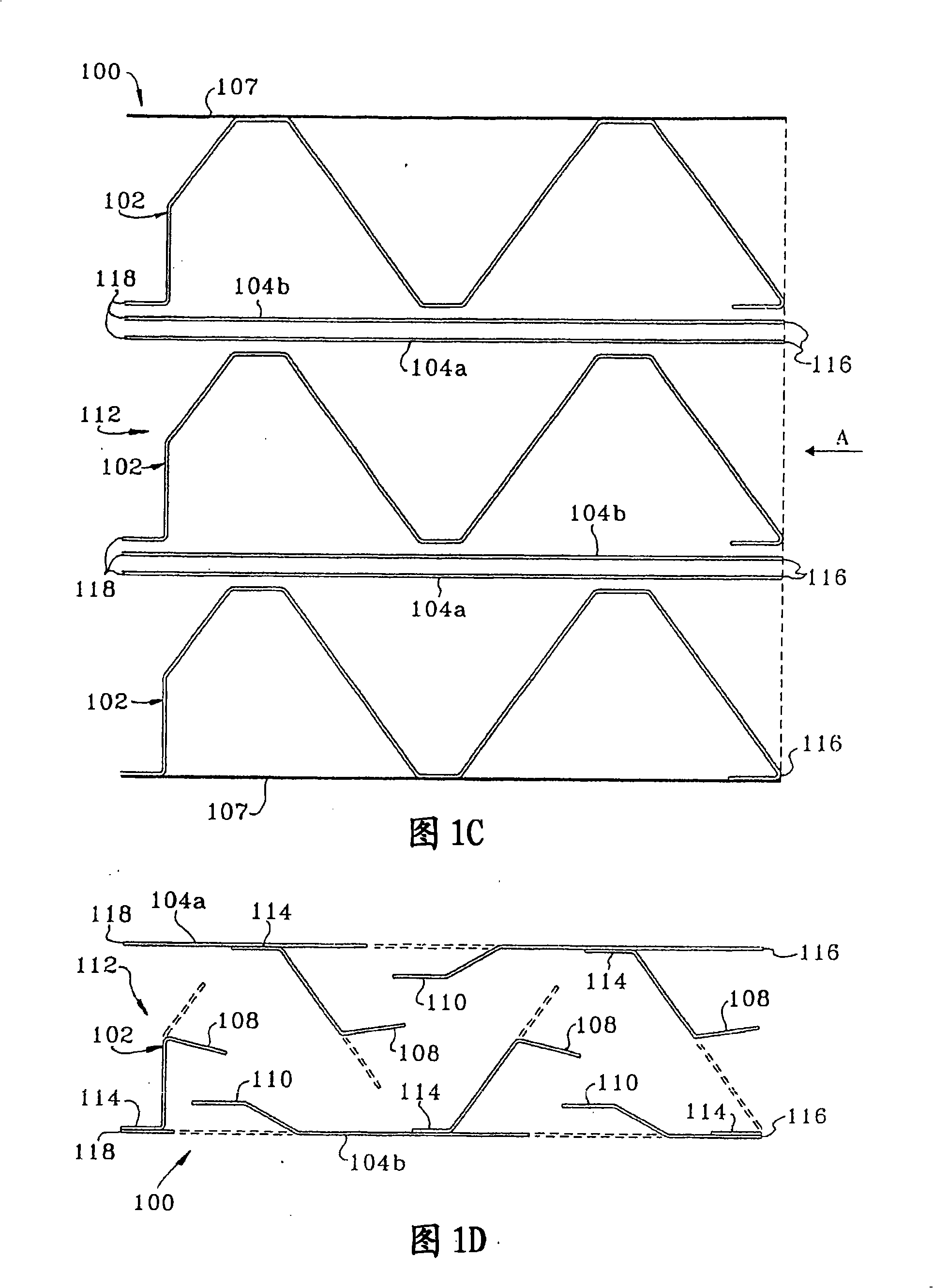
[0031] Figure 1A It is a plan view of the central part of the mist eliminator of the present invention, showing the arrangement of vanes or thin plates and integrated louvers that define the fluid flow path. The demister or demister 100 includes a plurality of corrugated sheets 102, a plurality of flat sheets 104a and 104b, and Figure 1B frame shown. Each corrugated sheet 102 includes a plurality of integral louvers 108 and the flat sheets 104a, 104b include integral louvers 110 . These vanes or sheets have a leading edge 116 near the inlet of the vapor liquid separator or demister and a trailing edge 118 at the vapor outlet.

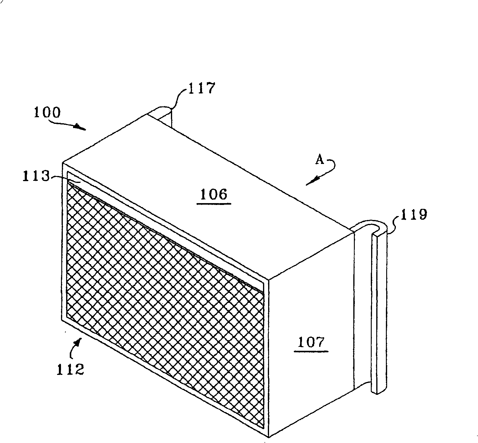
[0032] Figure 1B An embodiment of an outer frame is shown comprising a solid top panel 106 and two solid side walls 107 that are welded or otherwise securely fitted together to accommodate the corrugated sheet 102 and flat sheets 104a, 104b. The outer frame of this embodiment includes a perforated plate for vapor and liquid to enter and exit the d...


PUM


Abstract

The invention provides a vane-type mist eliminator device (100) having formed or corrugated sheets(102, 202, 302), flat sheets(104a,104b,204,304), and integral louvers(108, 110). The corrugated sheets and flat sheets are layered such that the arrangement of sheets and integral louvers creates at least one tortuous fluid flow channel from an inlet to a vapor outlet of the device. An outer casing or frame is sufficient to hold the sheets together.

Description

technical field [0001] This invention relates to a device for separating liquid and vapour. Background technique [0002] Many industrial processes use vapor-liquid separation devices to remove liquid droplets from vapor streams. "Vapor" and "gas" are used interchangeably in this application. In heat and / or mass transfer devices, vapor-liquid contact or phase changes often generate liquid droplets. An example of such a process is cocurrent fractionation in which a generally downwardly flowing liquid phase contacts an upwardly flowing gaseous phase. Although the general flow directions of the vapor and liquid are opposite during this process, co-current occurs when the vapor and liquid contact, i.e., the vapor entrains the liquid and flows upward toward a vapor-liquid separation device in which the The entrained liquid separates out. The liquid then flows down to the next stage and the vapor flows up to the previous stage. Air conditioning systems also typically require ...

Claims


Application Information

Patent Timeline
Patent Type & Authority Applications(China)
IPC IPC(8): B01D45/00
CPCB01D45/08B01D45/00
Inventor J·阿格内洛T·C·黑尔德魏因许占平A·J·穆克
Owner UOP LLC
Learn More