
Cmp retaining ring

A mechanical polishing and fixing ring technology, applied in the field of fixing rings, can solve the problems of increasing the cost of CMP, etc., and achieve the effect of improving connection strength, reducing wear and maintenance

Inactive Publication Date: 2008-12-24
ENTEGRIS INC
View PDF2 Cites 14 Cited by
  • Summary
  • Abstract
  • Description
  • Claims
  • Application Information

AI Technical Summary

Problems solved by technology

However, during polishing operations, some components of the equipment need to be replaced frequently, which greatly increases the cost of CMP

Method used


Image

  • Cmp retaining ring
  • Cmp retaining ring
  • Cmp retaining ring

Examples


Embodiment Construction

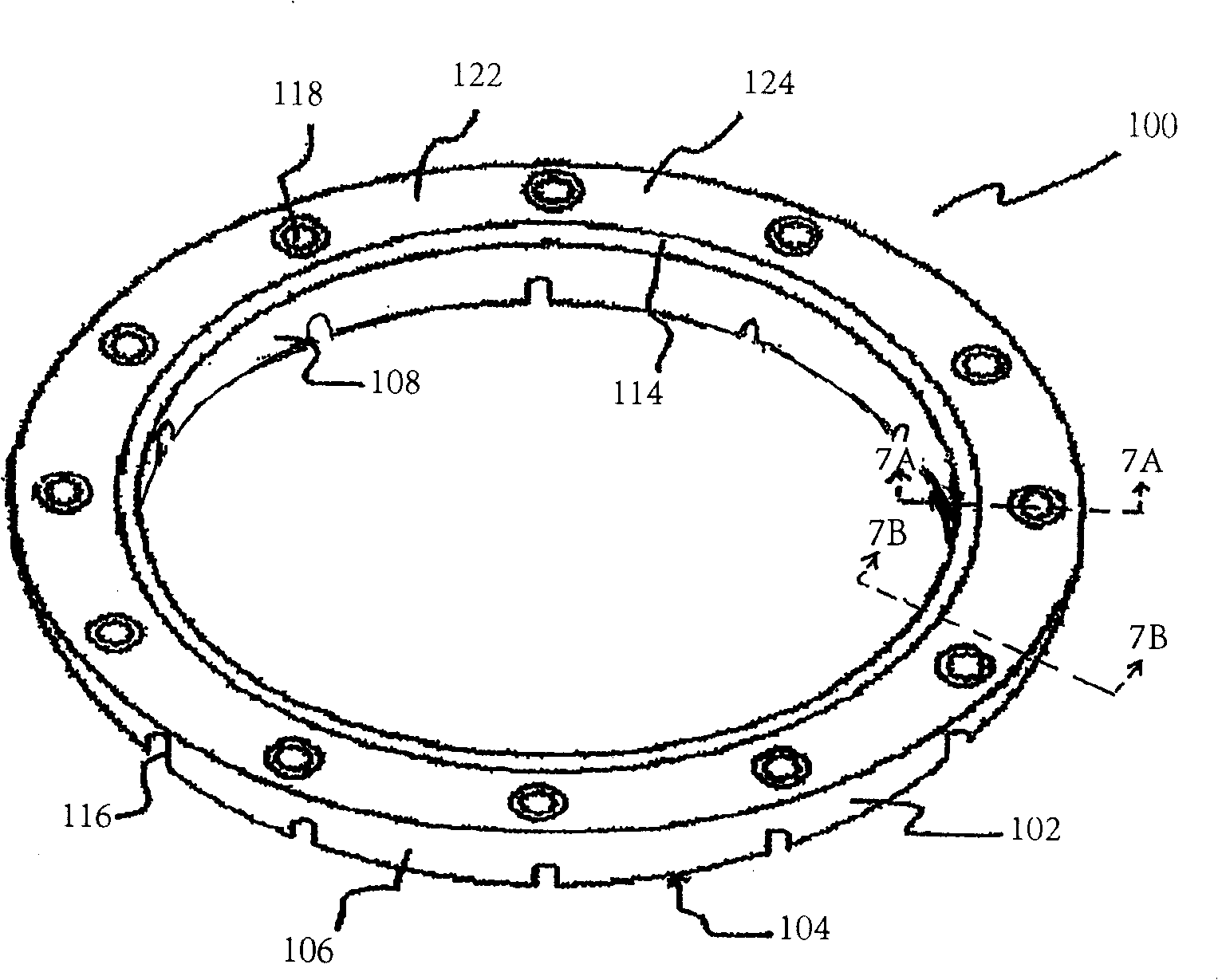
[0055] see figure 1 , a CMP retaining ring 100 according to an embodiment of the present invention can be seen. Retaining ring 100 includes a lower or base portion 102 and an upper or stem portion 122 .

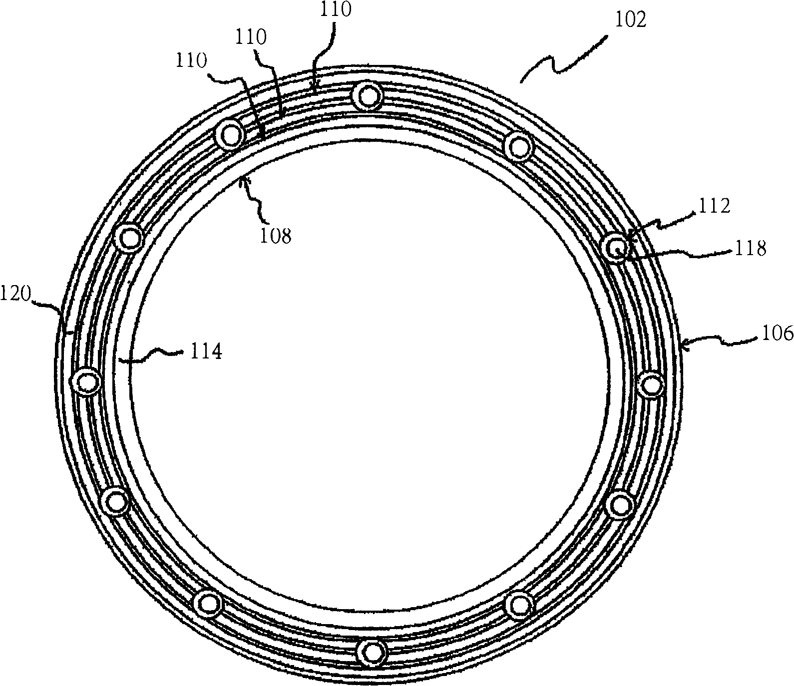
[0056] now refer to figure 2 and Fig. 4, an isolated view of the lower base 102 according to an embodiment of the present invention can be seen. The base 102 is generally formed of a flat bottom surface 104 , an outer surface 106 , an inner surface 108 , an upper edge 114 and a recess 120 . The recess 120 also includes a plurality of annular flanges 110 and a raised portion 112 having screw holes 118 . The flange 110 is used to form a secure connection when the upper trunk is overmolded onto the base, and to impart strength to the retaining ring 100 by preventing twisting or bending of said retaining ring. The base 102 also includes a flow channel or groove 116 extending from the outer surface 106 to the inner surface 108 . The flange 110 is coaxial with the fixing rin...


PUM


Abstract

Presented is an improved chemical mechanical polishing retaining ring. A representative embodiment comprises a base portion made from a wear-resistant plastic material, and an upper portion, or backbone portion, made from a stiffer and more wear resistant material. One of the base or backbone portion is preferably overmolded onto the other. The base portion can be generally defined by a flat pad-contacting surface, an outer surface, and an inner surface. The base portion can additionally include channels extending from the outer surface to the inner surface to facilitate transfer of slurry to and from the substrate to be polished during the process. One or both of the base portion or backbone portion further includes a plurality of circular ribs that serve to create additional bonding surface with the overmolded material.

Description

[0001] priority application [0002] This application claims priority to U.S. Provisional Patent Application No. 60 / 684,151, filed May 24, 2005, the disclosure of which is hereby incorporated by reference in its entirety, and also claims the title of invention filed on February 6, 2006 The priority of the same US Provisional Patent Application No. 60 / 765,995, the disclosure of which is hereby incorporated by reference in its entirety. technical field [0003] The invention relates to a retaining ring for pressing a semiconductor wafer in a chemical mechanical polishing device. Background technique [0004] An integrated circuit can be formed on a semiconductor substrate, especially a silicon wafer, by sequentially depositing a conductive layer, a semiconductive layer, and an insulating layer on the wafer. After the layers are deposited, circuit shapes can be etched on top. After depositing and etching a series of layers, the uppermost surface of the substrate may become m...

Claims


Application Information

Patent Timeline
IPC IPC(8): B24B29/00
Inventor 约翰·伯恩斯马克·V·史密斯马丁·L·福布斯杰夫里·J·金马太·A·富勒
Owner ENTEGRIS INC
Learn More