Marine fuel vapor separator with vent control device

A technology of gas separator and ventilation valve, which is applied in the direction of charging system, machine/engine, liquid fuel feeder, etc.

Inactive Publication Date: 2008-12-24
FEDERAL MOGUL CORP
View PDF0 Cites 2 Cited by
  • Summary
  • Abstract
  • Description
  • Claims
  • Application Information

AI Technical Summary

Problems solved by technology

However, these systems are passive configurations of the exhaust system, protecting only the open outlet line to the gas collection tank

Method used


Image

  • Marine fuel vapor separator with vent control device
  • Marine fuel vapor separator with vent control device
  • Marine fuel vapor separator with vent control device

Examples


Embodiment Construction

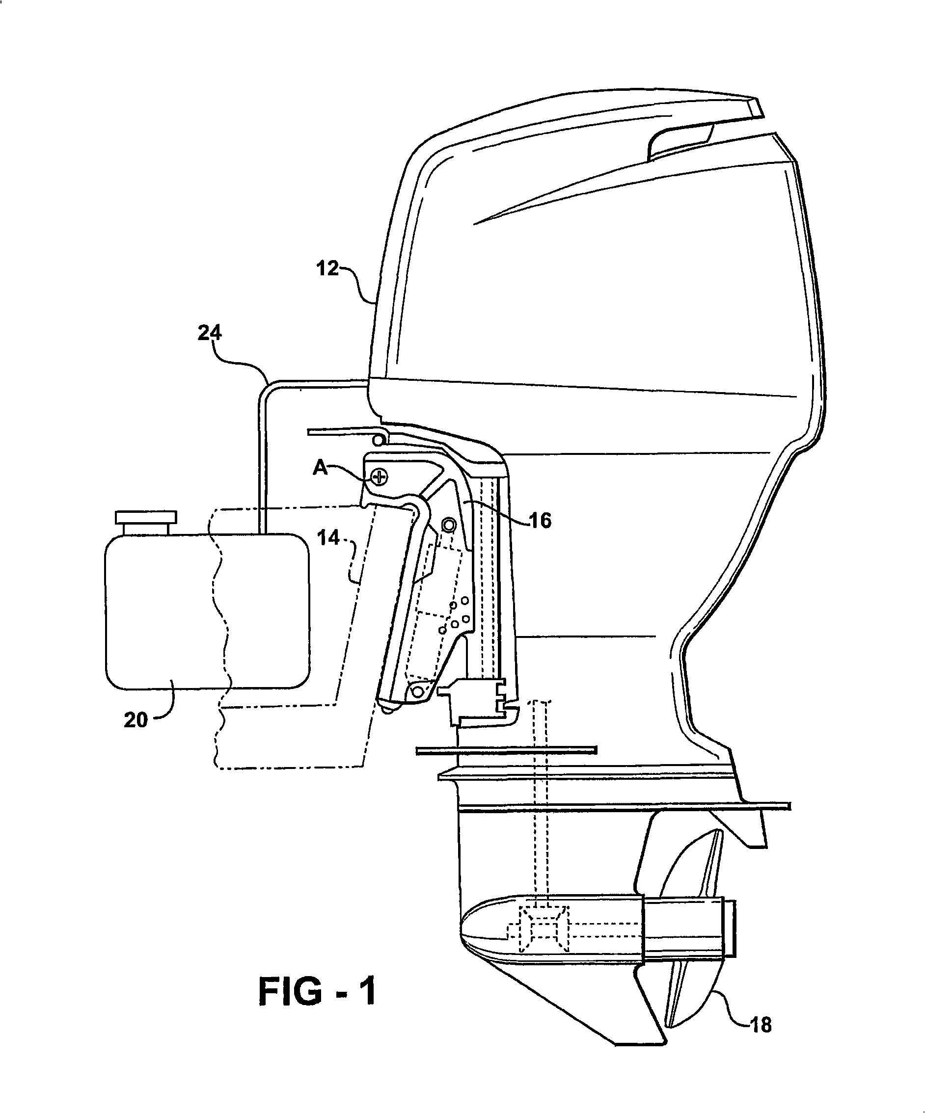
[0026] Referring to the drawings, wherein like numerals designate like or corresponding parts throughout the several figures, there is shown in FIG. 1 an outboard marine engine 12 attached to a transom 14 of a boat. Small outboard marine engines 12 of this type are typically mounted on a stand 16 so that the engine 12 can be quickly removed from the boat for transport and / or maintenance. The bracket 16 has an inclined structure, so that the motor head can be rotated into the boat, while the propeller 18 swings upwards away from the water, so as to start and move in a shallow state. For example, the motor 12 is pivotable about the A-axis between these use and non-use positions, as well for smooth control.

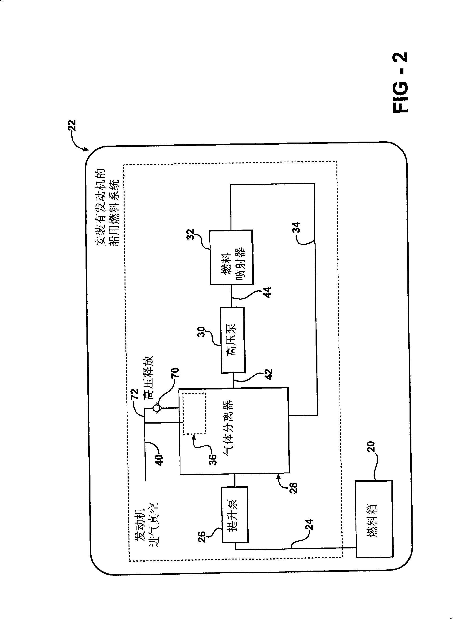
[0027] Engines of the type shown in Figure 1 typically run on liquid fuels like gasoline or ethanol. Liquid fuel is drawn from fuel tank 20 by an engine-mounted marine fuel system (shown generally at 22 in FIG. 2 ). With the exception of the fuel tank 20 and fuel supply li...


PUM


Abstract

A fuel supply system for an outboard marine engine includes a vapor separator (28) having a uni-directional vapor vent device (36) for preventing fuel leakage when the engine (12) is tipped on its side. The vapor separator (28) includes an enclosed interior chamber (50) which is filled with liquid fuel by a suction pump. A separate, high pressure pump transfers the liquid fuel from the interior chamber (50) to a fuel injection system (32) of the engine (12). The vapor vent device (36) includes a generally tubular casing having an enclosed top end permeated by an escape passage (84), and a float (94) slidably disposed within the casing (82) for movement toward and away from sealing engagement with the escape passage (84).

Description

[0001] Cross References to Related Applications [0001] This application claims priority to US Provisional Application Serial No. 60 / 727,151, filed October 14, 2005, entitled "Marine Oil Gas Separator with Vent Control". technical field [0002] The present invention relates to an air-oil separator for a marine engine fuel system to prevent fuel spillage when the engine rolls. Background technique [0003] Small outboard marine engines are usually removably mounted on the transom. These engines typically include an integrated fuel system that draws liquid fuel from the vessel's tank or tank under suction. Fuel is routed through a vapor body separator to liquefy or vent gases before being delivered at high pressure to the fuel injection system. [0004] Fuel vapor is a long recognized problem in the marine fuel industry. Mainly because the fuel is drawn out of the tank under negative pressure. Ship safety regulations require that the fuel delivered between the tank and t...

Claims


Application Information

Patent Timeline
Patent Type & Authority Applications(China)
IPC IPC(8): F02M37/20
Inventor 凯尔·迪安·埃科尔
Owner FEDERAL MOGUL CORP
Why Eureka
Try Eureka