

Precise extrusion molding method of thin wall long-pipe shaped parts bland and special mould
A technology of extrusion forming and long tubes, applied in the direction of metal extrusion dies, etc., can solve the problems of large machining volume, expensive parts, low utilization rate of finished materials, etc., and meet the requirements of reducing extrusion force and punch length , Dimensional accuracy and material utilization are improved, and the effect of reducing the cost of production equipment
- Summary
- Abstract
- Description
- Claims
- Application Information
AI Technical Summary
Problems solved by technology
Method used
Image

Examples
Embodiment Construction
[0014] Provide embodiment of the present invention in conjunction with accompanying drawing:
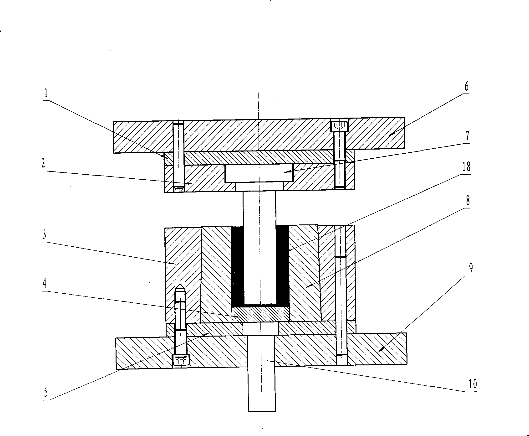
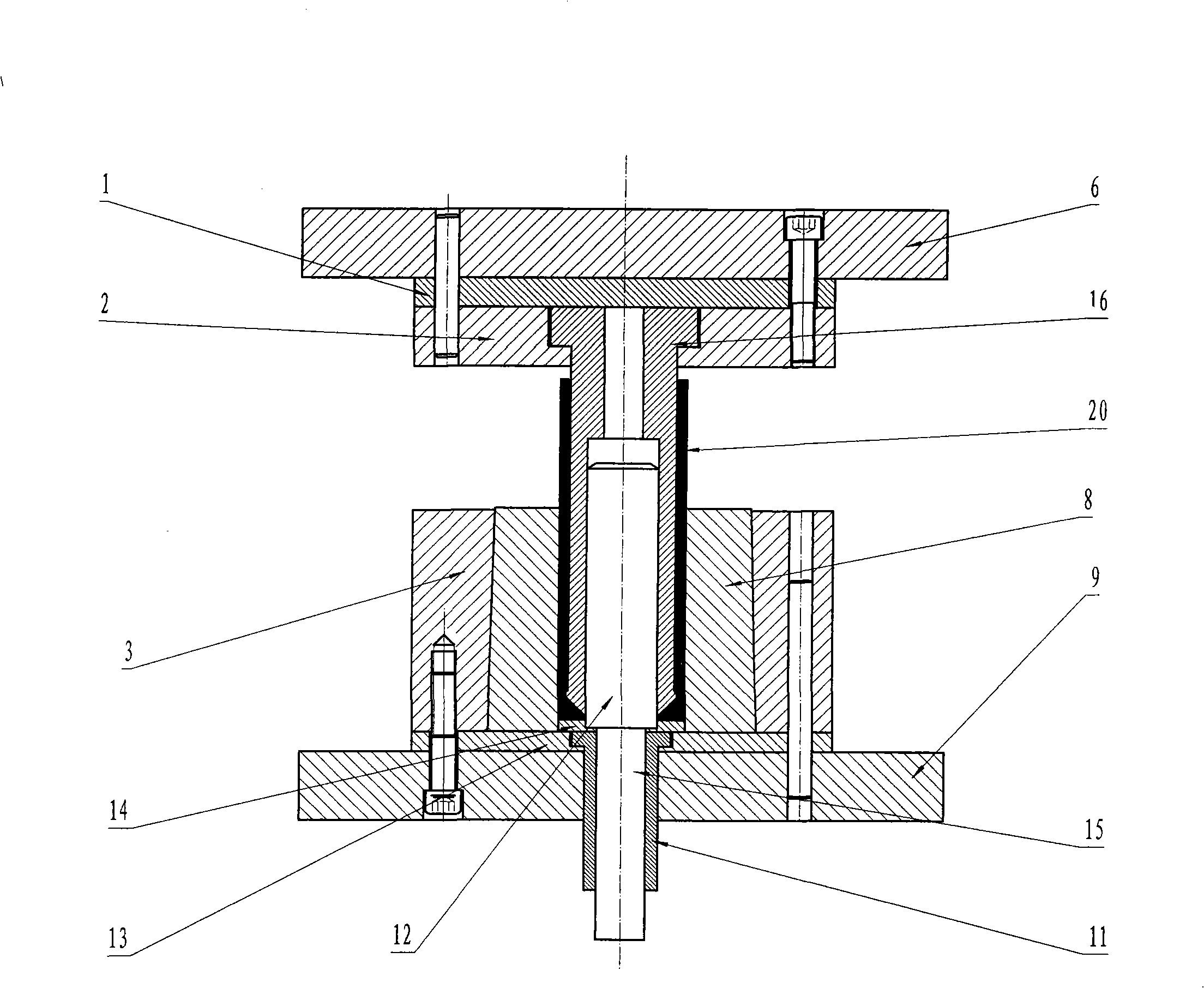
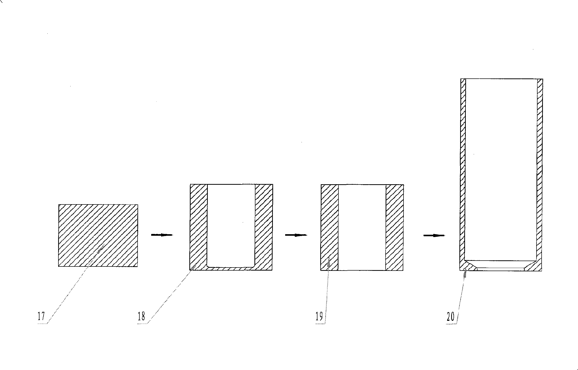
[0015] Such as figure 1 As shown, the die 8 is a cone with a narrow upper part and a wider lower part. The inner diameter of the through hole matches the diameter of the solid cylindrical blank 17, which is embedded in the inner cone cavity of the pre-tensioning ring 3 and fixed. The first-order punch 7 is a solid shaft with a step-shaped circular platform at the upper end, and its outer diameter matches the inner diameter of the first-order extruded tube blank 19 to be formed; The step round hole of the mold fixing plate 2 is fixed and the punch fixing plate 2 is connected with the lifting beam of the hydraulic press through the backing plate 1 and the upper template 6; the lower part is the die structure: the mold base of the die 8 includes: Pre-tightening ring 3, first-order ejector 4 and first-order die backing plate 5, lower template 9 and first-order ejector pin 10. The first...
PUM
 Abstract
Description
Claims
Application Information