Laminated moulding device and laminated moulding method

A technology of lamination device and laminate, applied in the direction of lamination device, lamination, lamination system, etc., can solve the problems of expensive plane stamping manufacturing cost, inability to form the overall thickness of parts, and complicated control of pressing mechanism.

Inactive Publication Date: 2008-12-31
MEIKI
View PDF2 Cites 7 Cited by
  • Summary
  • Abstract
  • Description
  • Claims
  • Application Information

AI Technical Summary

Problems solved by technology

[0009] In Patent Document 1, since a plurality of pressurization mechanisms or first and second pressurization mechanisms are provided, the parallelism between hot plates can be increased, and the thickness of the laminated board can be formed uniformly. cost, and the control of each pressurization mechanism is troublesome, etc.
In addition, in Patent Document 1, the movable template is slidably arranged on the four vertical connecting rods, and there is a small gap (0015) between the movable template and the connecting rods. There is a problem that the parallelism between the fixed die plate and the movable die plate cannot be ensured due to misalignment due to the sliding of each connecting rod, so there is a possibility that it may become difficult to form the entire thickness uniformly.
In addition, in Patent Document 1, due to problems such as the length and degree of bending of the oil delivery pipes leading from the oil pressure source to the four auxiliary cylinders, and the degree of wear of the sealing device of the cylinder, there is a problem that the intermediate laminated product is pressurized. The process is difficult to make the four auxiliary cylinders move completely synchronously
Therefore, in Patent Document 1, at the time of transition from the mold clamping process to the intermediate laminate pressurization process, that is, while the intermediate laminate is clamped between the hot plates 14, 15, the use of the auxiliary air cylinder is started. Pressurization, at the initial stage of pressurization at this time, there is a possibility that the pressurized pressure cannot be applied uniformly to the intermediate laminated product
[0010] In addition, in Patent Document 2, since the punching block of the plane press is provided with a supporting point node that can swing the head, when the punching block shakes the head due to the supporting point node, it cannot be held in parallel. The pressure surface of the two stamping blocks
In addition, in Patent Document 2, since the thickness of the resin composition layer is shaped to be constant by "surface profiling" (see FIG. 10 of Patent Document 2), it is not possible to separate the substrate and resin composition layer by layer. The entire thickness of the pressed part is molded to be constant (see FIG. 9 of Patent Document 2)
In addition, in Patent Document 2, since the thicker part of the substrate is in contact with a part of the stamping surface of the stamping block (0006), there is a resin composition layer that is easily deformed by heating and flows out from the substrate layer. , such a problem that a resin composition layer having a predetermined thickness cannot be formed

Method used


Image

  • Laminated moulding device and laminated moulding method
  • Laminated moulding device and laminated moulding method
  • Laminated moulding device and laminated moulding method

Examples


Embodiment Construction

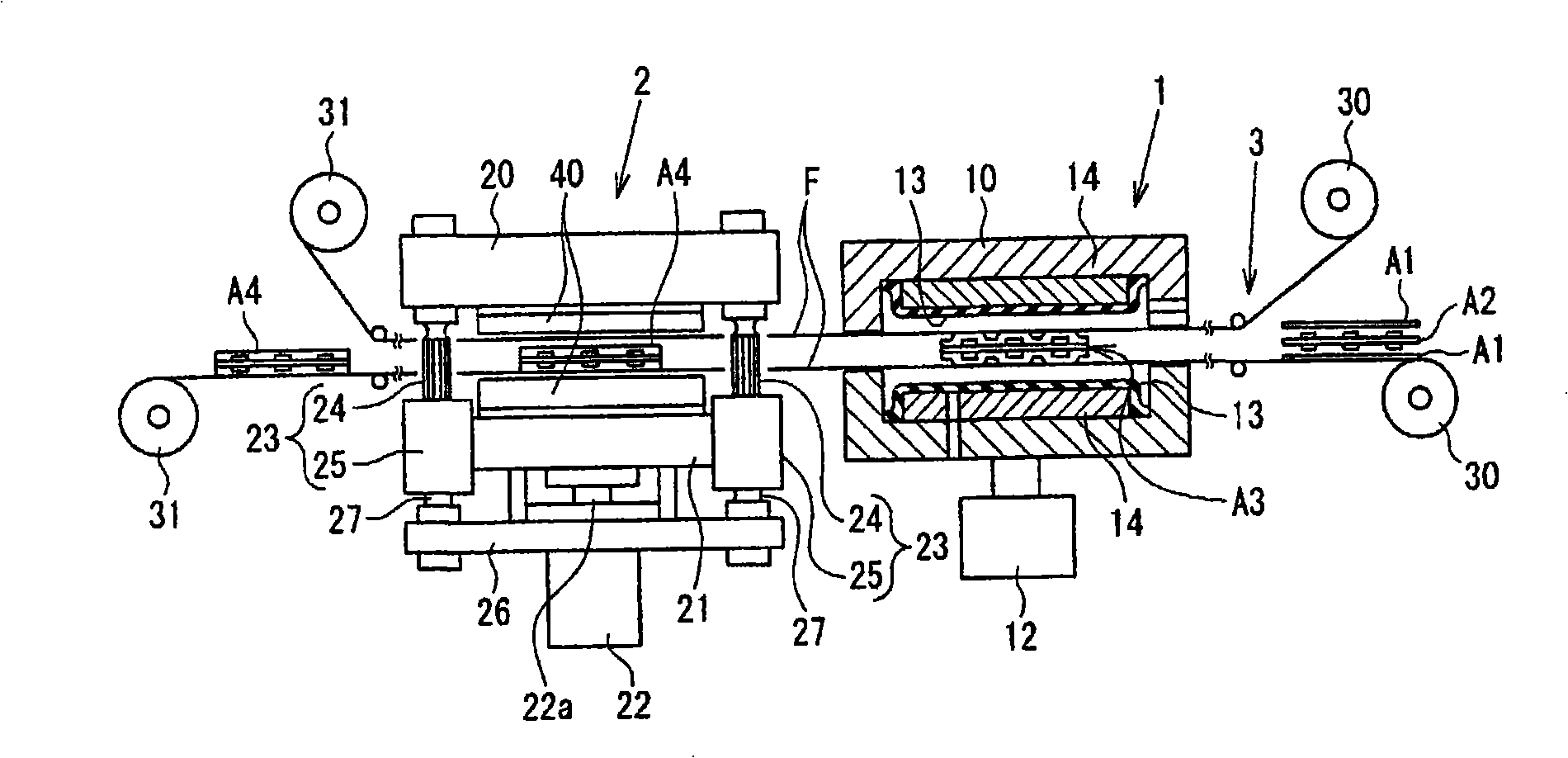
[0041] Below, based on Figure 1 to Figure 7 One embodiment of the present invention will be described in detail. In the drawings, the same symbols are attached to the same parts or corresponding parts. In the following description, an insulating layer as a lamination layer is laminated on a substrate layer with a circuit pattern formed thereon and has an uneven surface as a laminated material, so that the surface of the insulating layer is formed into a flat surface, and finally a composite substrate is manufactured. The situation is described.

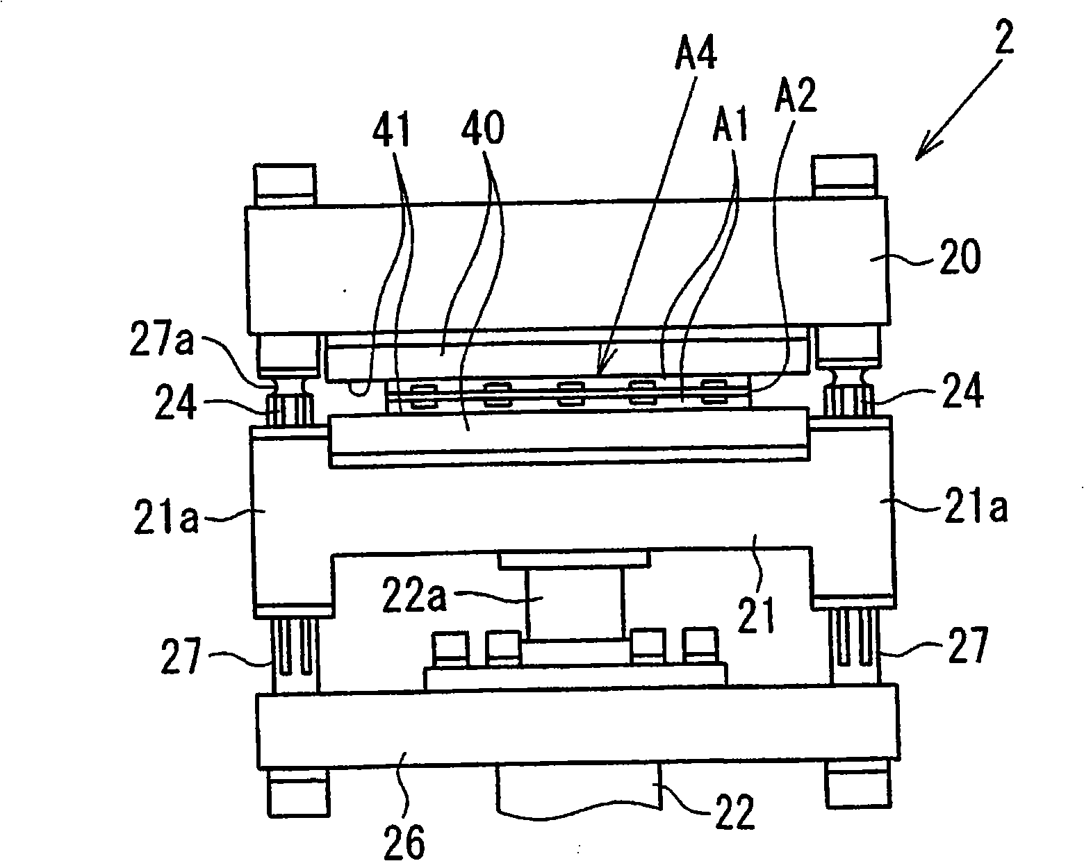
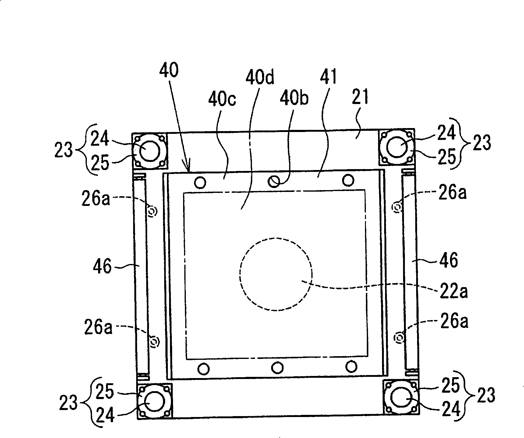
[0042] The lamination forming apparatus of the present invention generally includes: a lamination device 1 for laminating the intermediate laminate A3 by heating and pressing the laminate A1 and the laminate A2; a flat press 2 that presses the intermediate laminate A3 laminated by the apparatus 1 to shape its surface into a flat surface; In addition, the plane press 2 is equipped with: a fixed die plate 20 and a movable die plate ...


PUM

PropertyMeasurementUnit
hardnessaaaaaaaaaa
thicknessaaaaaaaaaa
hardnessaaaaaaaaaa

Abstract

The invention provides a lamination forming device and a lamination forming method for forming intermediate lamination products into lamination forming products with even thickness. The invention comprises a laminating apparatus (1) for laminating the lamination part(A1) and the laminated part(A2) to form the intermediate lamination product(A3), a plane press (2) for flat forming the surface by pressing the intermediate lamination product(A3) at the predetermined temperature, and a conveying unit (3). The plane press (2) comprises a fixed template (20), a movable template (21) and a translation unit (23) with a guiding movable template (32) making the movable template (21) move straightly in the vertical direction of the opposite surface. The translation unit (23) comprises multiple ball spline shafts (24), a corner part equipped on the movable template (21) and ball spline cylinders (25) respectively inserted by ball spline shafts (24).

Description

technical field [0001] The present invention relates to a lamination forming device and a lamination forming method. More specifically, the lamination forming device includes: a lamination device for laminating an intermediate laminated product by heating and pressurizing a laminated material and a laminated material ; a flat press for pressing an intermediate laminated product laminated by the laminating device at a predetermined temperature and forming its surface into a flat surface; and conveying the intermediate laminated product from the laminating device to the flat press The conveying unit of the machine, and the lamination forming method is to heat and pressurize the laminate and the laminated part by the laminating device to laminate the intermediate laminated product, and transport the intermediate laminated product from the laminating device to A flat press is a method in which the intermediate laminate is pressed at a predetermined temperature and its surface is f...

Claims


Application Information

Patent Timeline
Patent Type & Authority Applications(China)
IPC IPC(8): B32B39/00B32B38/18B32B37/15
CPCB29C43/146B29C43/36B29C43/52B29C53/18B29C2043/148B29C2043/189B29C2043/3405
Inventor 河野高幸
Owner MEIKI
Why Eureka
Try Eureka