Package film
A technology of packaging body and core body, applied in the directions of packaging, wrapping paper, transportation and packaging, etc., can solve problems such as heavy weight and achieve the effect of extending the quality assurance period
- Summary
- Abstract
- Description
- Claims
- Application Information
AI Technical Summary
Problems solved by technology
Method used
Image
Examples
no. 1 Embodiment approach
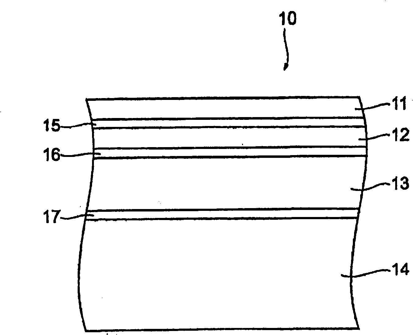
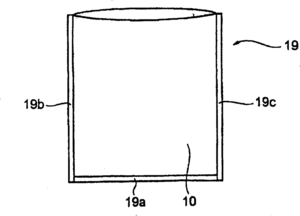
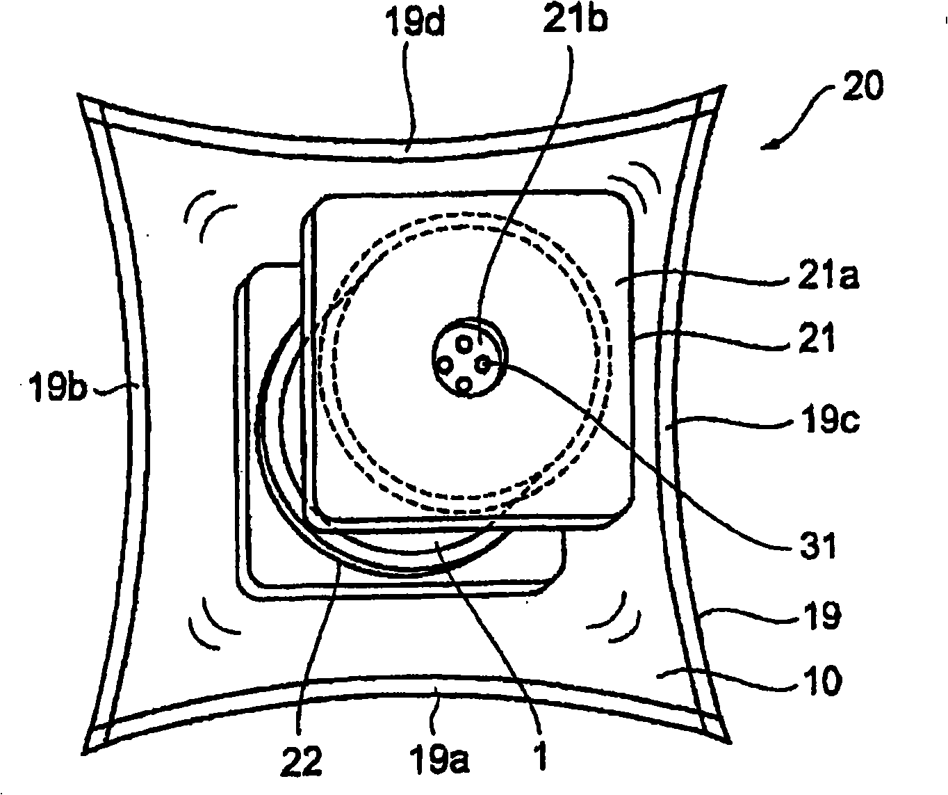
[0040] Next, embodiments of the packaging film for packaging electrode components and the electrode component package according to the present invention will be described with reference to the drawings.
[0041] [Parts for electrodes]
[0042] First, combine Figure 9 The electrode member 1 packaged according to the present invention will be described. Figure 9 It is a perspective view which shows the member 1 for electrodes.
[0043] The electrode member 1 is a member used in secondary batteries, especially lithium ion secondary batteries, double layer capacitors, and fuel cells, and is packed into a battery case after being cut and wound. Such an electrode member 1 is coated and rolled during the manufacturing process, so it is usually manufactured in a state wound on a winding core 2 made of aluminum or the like, and packaged in a state cut into an arbitrary width. of. Each roll weighs around 20kg.
[0044] In addition, the electrode component 1 is afraid of getting w...
no. 2 Embodiment approach
[0095] Below, combine Figure 7 and Figure 8 A second embodiment of the present invention will be described.
[0096] Figure 7 It is a figure which shows the component packaging body 40 for electrodes of this invention, Figure 8 is a diagram showing an application example thereof. In this embodiment, any and Figure 1 to Figure 4 as well as Figure 9 The same reference numerals are assigned to the same parts as those in the first embodiment shown, and detailed description thereof will be omitted.
[0097] Such as Figure 7 As shown, the electrode member packaging body 40 has a plurality of electrode members 1 wound on the winding core 2, buffer members 22 provided between the electrode members 1, and the electrode members 1 and the buffer members 22 are penetrated. A slide shaft 41 holding these, and a case 45 detachable from the slide shaft 41 .
[0098] Here, the winding core 2 wound with the member 1 for the electrode has a cylindrical shape with a central axis h...
no. 3 Embodiment approach
[0116] Below, combine Figure 10 ~ Figure 13 A third embodiment of the present invention will be described. The point of the third embodiment is to prevent lateral slippage of the wound layer of the electrode member wound around the core.
[0117]"Principles for preventing lateral slippage of wound layers"
[0118] Figure 10 It is an enlarged view of the main part partially cut away for explaining the principle of preventing the lateral slippage of the winding layer in the third embodiment, corresponding to Figure 7 A diagram of the interior of the housing. Figure 10 In the figure, in order to clarify the principle, the buffer member 120 is shown in section. In the illustrated example, three winding bodies 110 are held on the holding shaft (slide shaft) 104 . However, the number of wound bodies 110 is not limited thereto, and may be one or plural.
[0119] Such as Figure 11 As shown, each winding body 110 includes a hollow cylindrical core body 111 and a long sheet ...
PUM
 Abstract
Description
Claims
Application Information
 - R&D
- Intellectual Property
- Life Sciences
- Materials
- Tech Scout
- Unparalleled Data Quality
- Higher Quality Content
- 60% Fewer Hallucinations
Browse by: Latest US Patents, China's latest patents, Technical Efficacy Thesaurus, Application Domain, Technology Topic, Popular Technical Reports.
© 2025 PatSnap. All rights reserved.Legal|Privacy policy|Modern Slavery Act Transparency Statement|Sitemap|About US| Contact US: help@patsnap.com


