
Oil sending and receiving equipment for railway tanker

A technology of tank cars and railways, which is applied in the field of oil receiving and dispatching equipment for railway tank cars, which can solve the problems of high station construction costs, manual work, and low speed of deployment and withdrawal, and achieve the effect of strong emergency mobility and fast sending and receiving

Inactive Publication Date: 2008-12-31
HUBEI NO 3611 MACHINERY WORKS
View PDF0 Cites 9 Cited by
  • Summary
  • Abstract
  • Description
  • Claims
  • Application Information

AI Technical Summary

Problems solved by technology

Its disadvantages are that the construction cost is high; the second is that it is not suitable for wartime needs, and the oil cannot be transferred when the fixed oil unloading platform of the railway is damaged.
Although our army has been partially equipped with railway emergency recovery and emergency equipment, it directly affects railway transportation due to its complex unit, mainly relying on manual work, time-consuming and labor-intensive, low deployment and withdrawal speed, many operators required, and large operating area. Due to the wartime response speed and emergency support capability of oil, it has been difficult to popularize and apply

Method used


Image

  • Oil sending and receiving equipment for railway tanker
  • Oil sending and receiving equipment for railway tanker
  • Oil sending and receiving equipment for railway tanker

Examples


Embodiment Construction

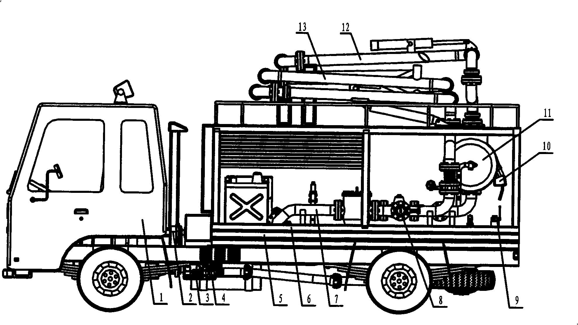
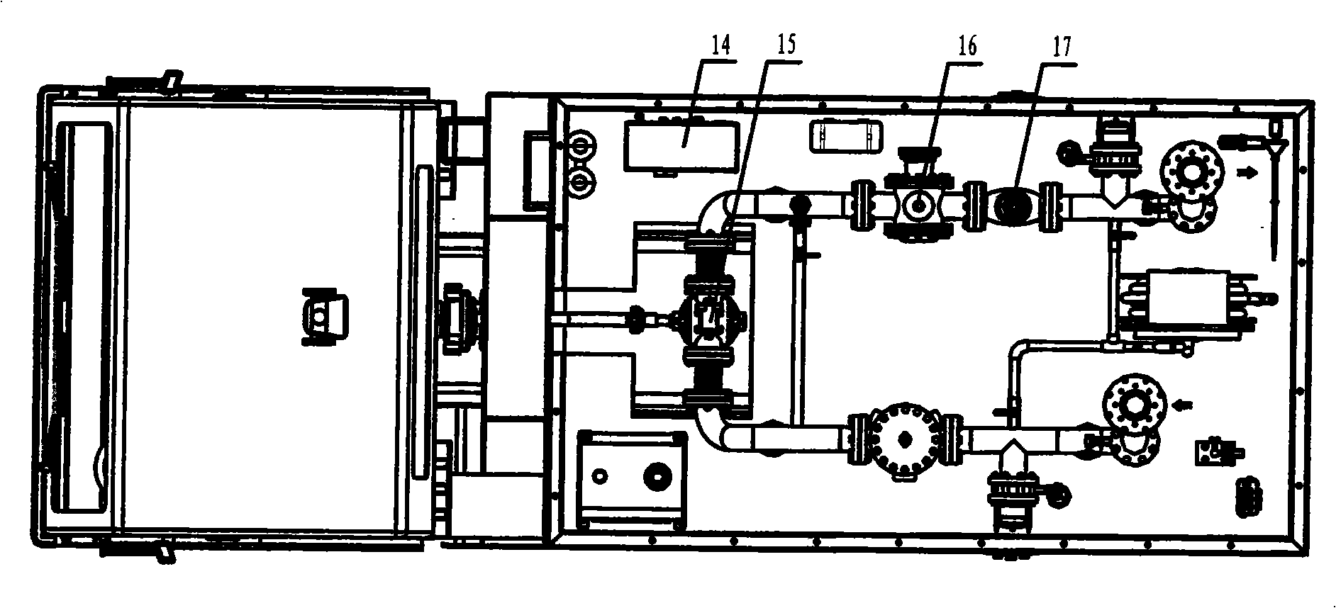
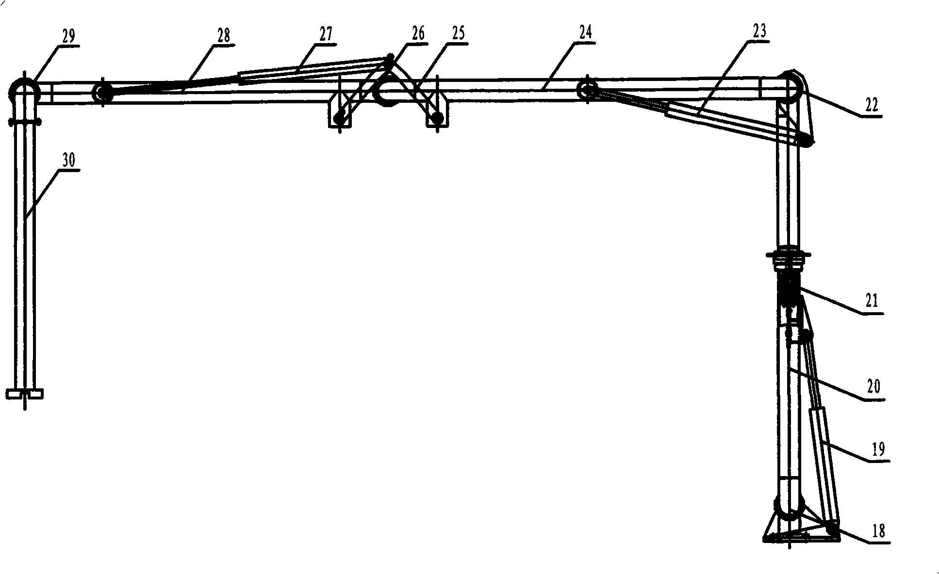
[0011] like figure 1 , figure 2 , image 3 shown. The present invention consists of an automobile chassis 1, a front clamping power take-off 2, a side power take-off 4, a box body 6, a unit and a pipeline system 7, a car tank top mounting crane 12, and a train tank roof unloading crane pipe hydraulic lifting device 13 Compositions. The vehicle chassis 1 is an existing military off-road vehicle chassis, and the box body 6 is fixed on the vehicle chassis 1 through the sub-frame 5 . The unit, the pipeline system, and the crane mounted on the top of the tank car are the prior art, which are the same as those on the existing fixed oil unloading platform.

[0012] The front clamp power take-off 2 is connected with the engine, the side power take-off 4 is connected with the gearbox, and the side power take-off 4 is connected with the gear pump 3. The dual power output device is used to solve the problem of the sliding vane pump 15 of the oil sending and receiving unit. And the ...


PUM


Abstract

The invention relates to an oil collecting and dispatching device of a railway tanker, belonging to the technical field of oil transfer equipment. The oil collecting and dispatching device essentially overcomes the problem that the measure that fixed oil drain platforms are built along railway lines for realizing oil transfer of train tankers has high station building cost and can not meet wartime demands. The device is essentially characterized in that the oil collecting and dispatching device comprises an automobile chassis; a front clamping power take off, a side power take off and a case which are fixed on the automobile chassis; a machine set and a pipe system which are installed in the case; a tanker top loading arm and a hydraulic lifting device of a train tanker top unloading arm which are arranged on the top of the case; the front clamping power take off is connected with an engine; the side power take off is connected with a gear-box; the hydraulic lifting device of the train tanker top unloading arm comprises four arms and gyrators connected among the arms; cylinders arranged between the adjacent arms and a multichannel conversion valve for controlling the cylinders; a gyration limit device and an amplitude link mechanism which are arranged on the arms; a gear pump which is connected with the side power take off; the oil collecting and dispatching device is mainly applied to temporary oil loading and unloading sites of special service railroads.

Description

technical field [0001] The invention belongs to the technical field of oil conveying equipment. In particular, it relates to a method that can realize the fast sending and receiving function of oil in a train tanker at a temporary oil loading and unloading site on a special railway line at any time, and can directly transport it to an automobile oil tanker, so as to improve the emergency maneuverability and adapt to the emergency mobile combat troops under the high-tech conditions in the future. The rapid supply of oil is required, and it can also be used in railway tankers for civil occasions to send and receive oil. Background technique [0002] At present, the transportation of oil in my country mainly relies on railway train tank cars, and fixed oil unloading pallets are established along the railway to realize the transportation of oil. The fixed unloading pallet includes the pallet building located along the railway line and higher than the top of the train tank car, ...

Claims


Application Information

Patent Timeline
Patent Type & Authority Applications(China)
IPC IPC(8): B67D5/01B67D7/00
Inventor 白光王雷熊学军王钧盛张瑜
Owner HUBEI NO 3611 MACHINERY WORKS
Learn More