Al technical title is built by PatSnap Al team. It summarizes the technical point description of the patent document.
A Hall thruster and longevity technology, applied to instruments, scientific instruments, measuring devices, etc., can solve the problems of high cost and long time, and achieve the effect of reducing experiment time and cost
Inactive Publication Date: 2008-12-31
HARBIN INST OF TECH
View PDF0 Cites 13 Cited by
Summary
Abstract
Description
Claims
Application Information
AI Technical Summary
This helps you quickly interpret patents by identifying the three key elements:
Problems solved by technology
Method used
Benefits of technology
Problems solved by technology
[0003] The invention provides a method for estimating the life of a Hall thruster to solve the pro
Method used
Image
Click on the blue label to locate the original text in one second.
Reading with bidirectional positioning of images and text.
Examples
specific Embodiment approach 1
[0009] Specific implementation mode one: this implementation mode is completed by the following steps:
[0010] 1. Ion bombardment of the easy-to-sputter ceramic tube, the bombardment thickness of the ceramic tube surface within the time t is h, and the angular sputtering coefficient of the easy-to-sputter ceramic tube Y′(θ)=n 1 ·Y'(θ), energy sputtering coefficient S(E)=n 2 ·S(E), pipe surface density N=n 3 N, Y′(θ), S(E) and N are the angular sputtering coefficient, energy sputtering coefficient and tube surface density of the Hall thruster channel ceramic tube, respectively, n 1 , n 2 , n 3 is a value greater than 1, θ is the incident angle of ions bombarding the wall and is a constant value;
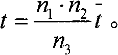
[0011] 2. According to the radial erosion rate formula of the Hall thruster and the thickness formula of the wall surface being eroded, the life of the Hall thruster with a pipe thickness of h can be deduced t = n ...
specific Embodiment approach 2
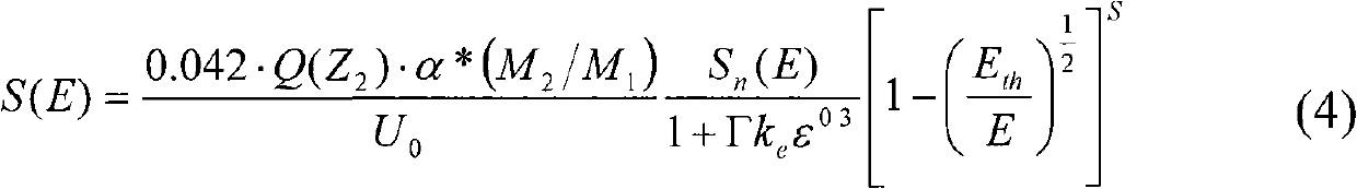
[0013] Specific implementation mode two: combination figure 1 Describe this implementation mode, the difference between this implementation mode and specific implementation mode 1 is: this implementation mode in step 1:
[0014] S ( E ) = 0.042 · Q ( Z 2 ) · α * ( M 2 / M 1 ) U 0 S n ( E ) 1 ...
specific Embodiment approach 3
[0047] Specific embodiment three: the difference between this embodiment and specific embodiment one is: the radial erosion rate formula of the Hall thruster in step two of this embodiment is:
[0048] q = J i ⊥ S ( E ) Y ′ ( θ ) cos ( θ ) N - - - ( 1 )
[0049] Among them, J i⊥ is the ion current density that collides with the wall.
[0050] By changing the process, the change of density can be easily realized, for example, by changing the hot pressing pressure, the ...
PUM
Abstract
The invention discloses an estimation method of the service life of a Hall thruster, which relates to a method for estimating the service life of the Hall thruster. The invention solves the problem that the current full service life test to the Hall thruster has long time consumption and great cost consumption. Ionic bombardment is carried out to an easy sputtering ceramic tube, and within the time t, the bombardment thickness of the surface of the ceramic tube is h, wherein, the angle sputtering coefficient of the easy sputtering ceramic tube Y' (Theta) is equal to n1 multiplied by Y' (Theta), the energy sputtering coefficient S(E) is equal to n2 multiplied by S(E), and the tube surface density N is equal to n3 multiplied by N, wherein, Y' (Theta), S(E) and N are respectively the angle sputtering coefficient, the energy sputtering coefficient and the tube surface density of the ceramic tube of the Hall thruster passage; the service life of the Hall thruster with the passage thickness of h can be deduced according to the radial corrosion rate equation and the equation of the corroded thickness of the wall surface of the Hall thruster, that is, t is equal to (n1 multiplied by n2 divided by n3) multiplied by t. The method can carry out effective estimation and evaluation of the full service life of the Hall thruster within a short time, thus greatly reducing experimental time, lowering cost, and having the advantage of being direct and reliable, and the reliability of the method is higher than the service life prediction carried out to the thruster by adopting numerical calculation.
Description
technical field [0001] The invention relates to a method for estimating the lifetime of a Hall thruster. Background technique [0002] Due to the high specific impulse, efficiency and operational stability of Hall thrusters, Hall thrusters have been applied in various satellites. The life requirement of the thruster is even more stringent, and also requires the thruster to have a longer life for deep space exploration missions. The most important factor limiting the life of the Hall thruster is the sputtering erosion of the ceramic wall of the channel under the bombardment of energetic ions. At present, when studying the life of the Hall thruster, the time when the channel wall of the Hall thruster is eroded by ions and the magnetic poles are exposed to the plasma flow is generally taken as the end of the life of the Hall thruster. Therefore, it is important to study the life of the Hall thruster. It is converted into the study of the sputtering erosion of the channel wall...
Claims
Application Information
Patent Timeline
Application Date:The date an application was filed.
Publication Date:The date a patent or application was officially published.
First Publication Date:The earliest publication date of a patent with the same application number.
Issue Date:Publication date of the patent grant document.
PCT Entry Date:The Entry date of PCT National Phase.
Estimated Expiry Date:The statutory expiry date of a patent right according to the Patent Law, and it is the longest term of protection that the patent right can achieve without the termination of the patent right due to other reasons(Term extension factor has been taken into account ).
Invalid Date:Actual expiry date is based on effective date or publication date of legal transaction data of invalid patent.