

Touch control display and its drive method
A technology of a touch display device and a driving method, which is applied to static indicators, instruments, electrical digital data processing, etc., can solve the problems of high energy consumption and low reliability of display devices, and achieve energy saving, reliability improvement, The effect of avoiding misuse
- Summary
- Abstract
- Description
- Claims
- Application Information
AI Technical Summary
Problems solved by technology
Method used
Image

Examples
Embodiment Construction
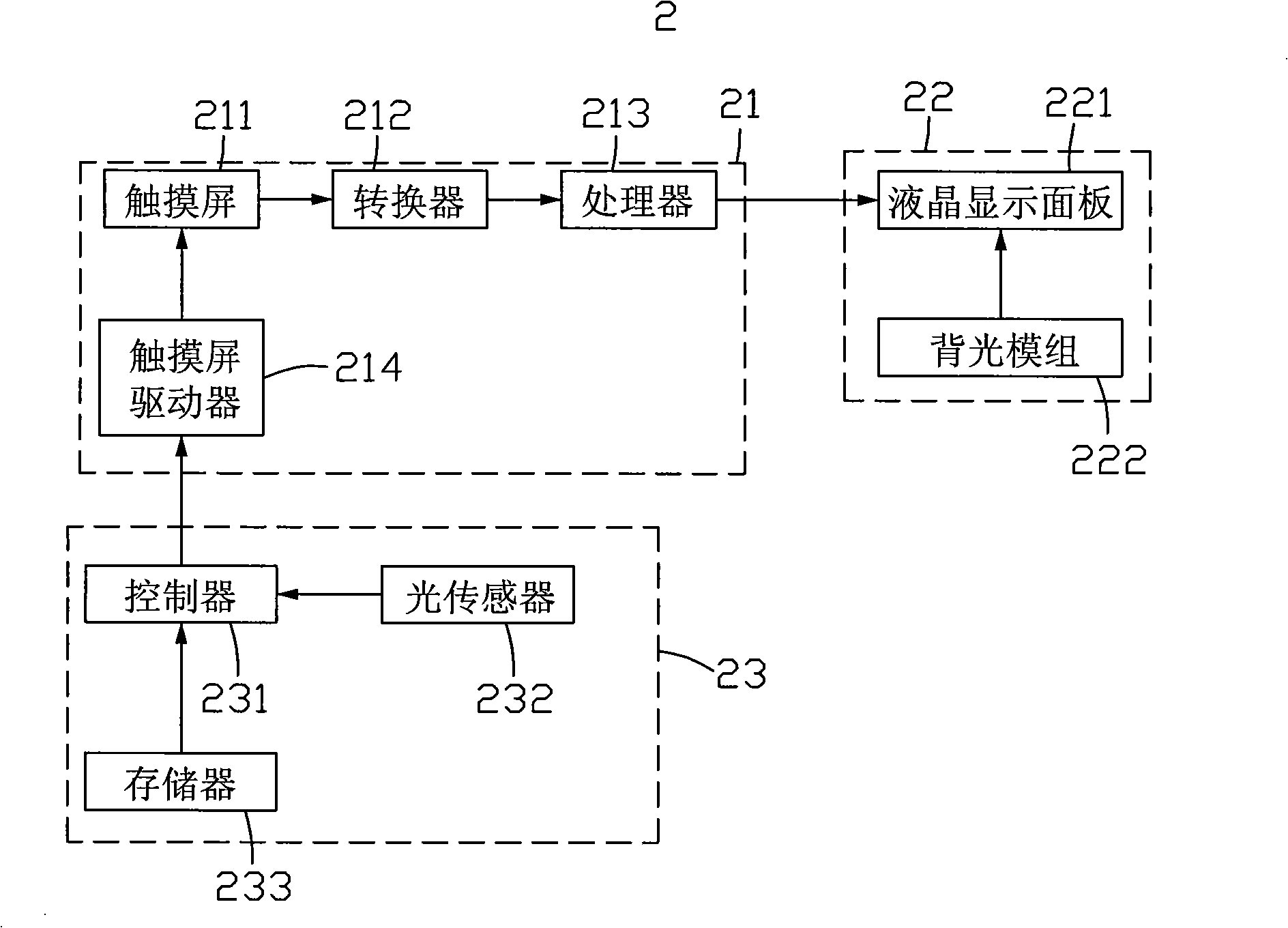
[0020] see figure 2 , which is a schematic structural diagram of the first embodiment of the touch display device of the present invention. The touch display device 2 includes a touch unit 21 , a display unit 22 and a detection control unit 23 .
[0021] The display unit 22 includes a liquid crystal display panel 221 and a backlight module 222 , the backlight module 222 provides sufficient backlight for the liquid crystal display panel 221 to display images.
[0022] The touch unit 21 includes a touch screen 211 , a converter 212 , a processor 213 and a touch screen driver 214 . The touch screen driver 214 is used to drive the touch screen 211 to work. Driven by the touch screen driver 214 , the touch screen 211 receives an external pressure signal and transmits the pressure signal to the converter 212 . The converter 212 converts the pressure signal into a digitized position signal representing the pressure position, and transmits the digitized position signal to the proc...
PUM
 Abstract
Description
Claims
Application Information