Wind turbine rotor blade comprising a trailing edge section of constant cross section

A technology for blades and blade profiles, applied in the field of profile series, to solve problems such as inaccuracies, damage, tolerances, etc.

Active Publication Date: 2009-01-07
LM GLASSFIBER
View PDF1 Cites 12 Cited by
  • Summary
  • Abstract
  • Description
  • Claims
  • Application Information

AI Technical Summary

Problems solved by technology

The final construction of the trailing edge is therefore subject to considerable inaccuracies and tolerances, the production process is also work-intensive and time-consuming, and as far as the glued blade parts are concerned, there are problems related to the working environment due to dust from the sanding process. question
[0006] Furthermore, the trailing edge of the wing / blade constitutes a rather fragile component which is easily and frequently damaged during e.g. transport and assembly

Method used


Image

  • Wind turbine rotor blade comprising a trailing edge section of constant cross section
  • Wind turbine rotor blade comprising a trailing edge section of constant cross section
  • Wind turbine rotor blade comprising a trailing edge section of constant cross section

Examples


Embodiment Construction

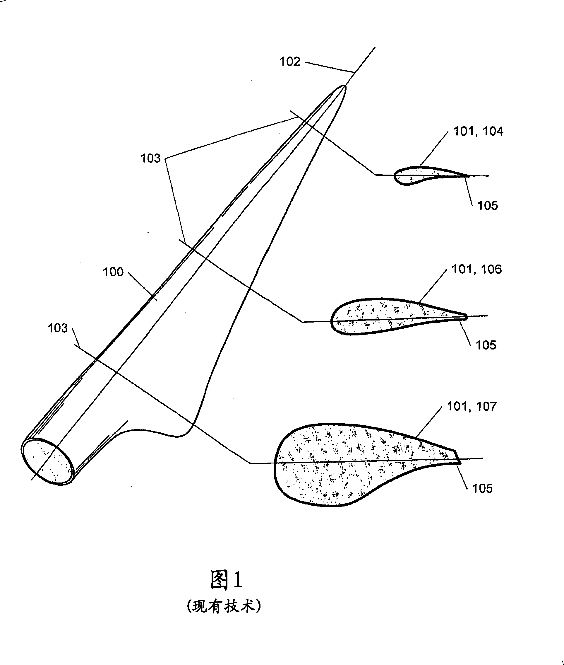
[0027] Fig. 1 shows a wind turbine blade 100 according to the prior art. The blade is depicted by a number of cross-sections 101 drawn alongside the blade. Each profile 101 indicates the outer contour of the blade 100 in the form of a cross-sectional view corresponding to a cross-section taken along the marking line 103 at a given position on the blade longitudinal axis 102 . Section families for aircraft wings usually consist of sections of the same type, and then the section size changes towards the outside of the wing. This is not usually the case for wind turbine blades, which can be given by a series of sections characterized by different section patterns, and therefore the blade surface is interpolated or blended between sections to create a smooth transition between the different sections . This is illustrated by the blade shown in FIG. 1 , which is defined by a profile 104 characterized by a sharp trailing edge 105 at the extreme point of the blade tip. The advantag...


PUM


Abstract

A wind turbine rotor blade comprising a series of profiles is presented, which series of profiles comprises a number of profiles describing the outline of the blade transversally of its longitudinal axis, wherein some of the profiles of the series of profiles comprise approximately the same profile rear edge which describes at least a portion of the rear edge of the blade. The rear edge of the blade is configured in one piece and / or of a flexible material. Moreover a method of designing a series of profiles for a wind turbine rotor blade is presented.

Description

technical field [0001] The invention relates to a series of sections for at least a part of a blade comprising several sections describing the profile of the blade transversely with respect to the longitudinal axis of the blade. The invention also relates to a method of designing a series of profiles and a blade featuring such a series of profiles. Background technique [0002] Blades or wings for airplanes, helicopters, wind turbines etc. are made up of a series of profiles which describe the cross-section at different positions of the blade / wing along its length. These profiles are determined based on parameters such as the optimum lift coefficient at a specific height / width ratio, or more generally for wind turbine blades, to provide maximum power production at a specific rotational speed. Aircraft wings are generally defined by the principle that all cross-sections have the same shape but different dimensions. This is not the case with wind turbine blades, which are ty...

Claims


Application Information

Patent Timeline
Patent Type & Authority Applications(China)
IPC IPC(8): F03D1/06
CPCF03D1/0675F05B2280/4004F05C2225/02F05B2240/311F03D1/0641F05B2240/301Y02E10/721Y02E10/72
Inventor P·格雷博
Owner LM GLASSFIBER
Why Eureka
Try Eureka