
Wireless sensing monitoring system

A monitoring system, wireless sensing technology, applied in the direction of radio transmission system, transmission system, diagnosis, etc., can solve the problem that the sound and light alarm system is not suitable, and achieve the effect of improving quality and service level

Inactive Publication Date: 2011-11-02
徐菲
View PDF3 Cites 1 Cited by
  • Summary
  • Abstract
  • Description
  • Claims
  • Application Information

AI Technical Summary

Problems solved by technology

[0007] The present invention has beneficial effects as follows: firstly, it is a wireless sensor monitoring system device, and the position where the sensor is placed will not affect the effect of the alarm, which effectively solves the problem that the general sound and light alarm system is not suitable for hospitals and nursing centers. problem; the second is that it can conveniently set up a networked and centralized sensor monitoring system, and it also has a position tracking function, which is suitable for institutional and large-scale applications; the third is that it also has a calling function on the sensor side to solve The special needs of different patients or used in emergency situations; Fourth, the wireless display in the ward and the data terminal in the monitoring center also have a voice intercom function, which is a direct and effective communication method, and is an important tool for sensor monitoring. A necessary supplement to the system; Fifth, the data terminal can be further connected with the computer to realize unified realization and log-style recording and filing of all sensors in the system, so as to improve the quality and service level of the monitoring system

Method used


Image

  • Wireless sensing monitoring system
  • Wireless sensing monitoring system
  • Wireless sensing monitoring system

Examples

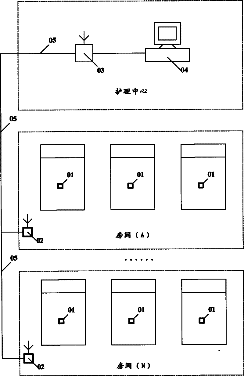

Embodiment Construction

[0024] The present invention will be further described below in conjunction with the accompanying drawings.

[0025] Please refer to figure 1 As shown, this is a schematic diagram of the network structure of the wireless sensor monitoring system device according to the embodiment of the present invention. Generally speaking, a monitoring system will have a nursing center and multiple wards (rooms), and one or more sickbeds (beds) are usually arranged in one room, and there are N rooms in this embodiment, and each room There are three beds. In this embodiment, a wireless sensor 01 is configured for each bed, and a wireless display 02 is configured for each room, and a remote data terminal 03 is also configured for the nursing center. The wireless sensor 01 and the wireless display 02 are connected by radio frequency wirelessly, and the wireless display 02 and the remote data terminal can be connected by radio frequency wirelessly (with antenna), or by wired connection or pow...


PUM


Abstract

The embodiment of the invention provides a wireless sensing monitor system, which comprises a wireless sensor and a wireless display device; the wireless sensor comprises a sensing input device, a sensor ID and a wireless emitting device. When the sensor enters into the triggering state, the sensor ID is sent by the wireless emitting device. The wireless display device comprises a wireless receiving device, a sensor ID synchronous list, a data processing device and a display device; when the display device makes comparison with the ID in the synchronous list after receiving the sensor ID which is sent by the sensor, the triggering sensor information is displayed on the display device if the sensor ID is correlated with the ID in the synchronous list. The embodiment of the invention realizes low cost and the function of networking system monitor through the wireless sensing and wireless communication technology, and especially provides an electronic urine induction and monitor system suitable for the institutions such as the hospitals, the homes for the aged, the nursing centers and the like.

Description

technical field [0001] The invention relates to a wireless sensor monitoring system, in particular to a wireless monitoring network system device suitable for realizing wireless urine wetness sensing and alarm functions in disposable diapers. Background technique [0002] Disposable diapers are a hygienic product that is very popular both in the home and in hospitals and care centers. Disposable diapers are no doubt more hygienic and convenient than traditional diapers. Disposable diapers are usually composed of a dry layer (inner layer), a moisture-absorbing layer (interlayer) and an impermeable layer (outer layer). The dry layer is the innermost layer of the diaper. When the user pulls urine in the diaper, the urine can pass through The dryness layer is absorbed by the moisture-absorbing layer so that the dryness layer is kept dry. However, this kind of dryness is relative. On the one hand, the moisture absorption capacity of the hygroscopic layer is limited, and on the ...

Claims


Application Information

Patent Timeline
Patent Type & Authority Patents(China)
IPC IPC(8): A61B19/00H04B7/00G01N27/00A61F13/42
Inventor 黄更徐菲
Owner 徐菲
Learn More