
Hybrid drive system

A driving system and hybrid technology, applied in the direction of hybrid vehicles, power devices, air pressure power devices, etc., can solve the problems of unfavorable power output, driving mode and single function, etc., and achieve improvement and optimization of fuel consumption and harmful emission Transmission efficiency and the effect of reducing fuel consumption

Active Publication Date: 2009-01-14
BYD CO LTD
View PDF1 Cites 35 Cited by
  • Summary
  • Abstract
  • Description
  • Claims
  • Application Information

AI Technical Summary

Problems solved by technology

This will make the driving mode and function of the entire driving system single, which is not conducive to achieving the best power output

Method used


Image

  • Hybrid drive system
  • Hybrid drive system
  • Hybrid drive system

Examples


Embodiment Construction

[0018] The specific embodiments of the present invention will be described in detail below in conjunction with the accompanying drawings.

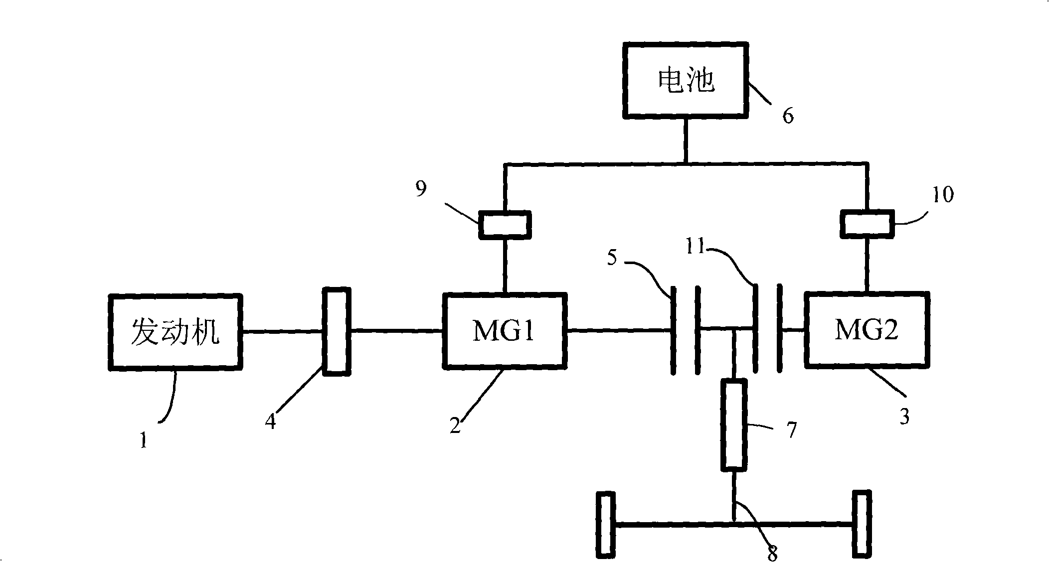
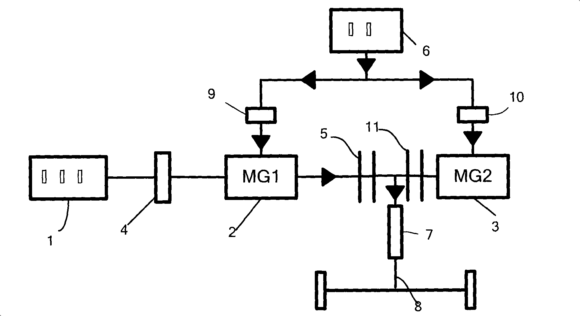
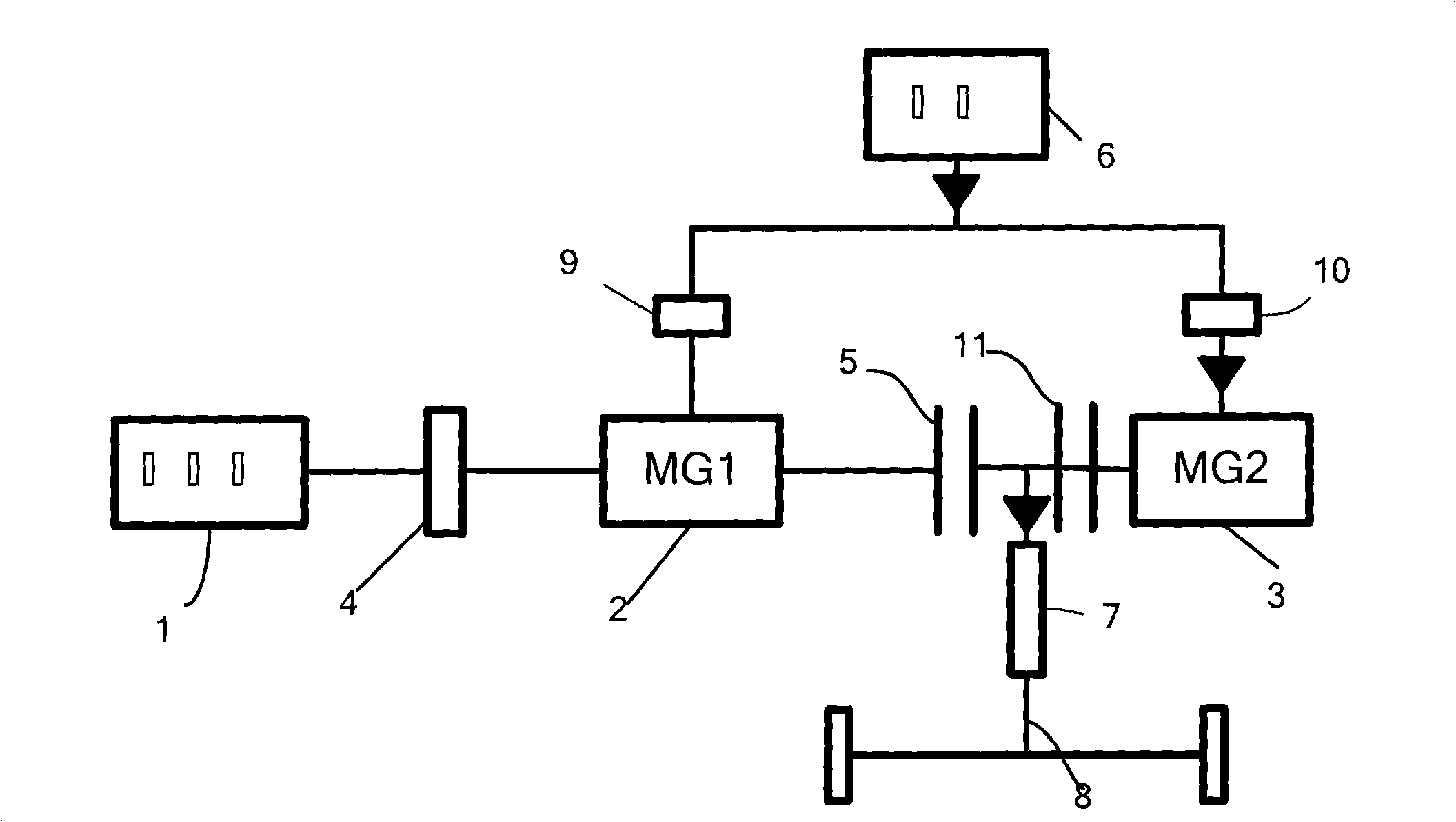
[0019] Such as figure 1 As shown, a hybrid drive system according to the present invention includes an engine 1, a first motor (MG1 shown in the figure) 2 and a second motor (MG2 shown in the figure) 3 electrically connected to the battery pack 6 , a transmission 4, a first clutch 5 and a second clutch 11 and a transmission shaft 8, wherein: the engine 1, the transmission 4, the first motor 2, the first clutch 5, the second clutch 11 and the second motor 3 are connected in sequence, And the transmission shaft 8 is connected between the first clutch 5 and the second clutch 11 .

[0020] The drive system may also include a constant speed ratio reduction mechanism 7 arranged between the first clutch 5 and the second clutch 11 , the output power of the mechanism 7 is output to the wheels through the transmission shaft 8 .

[0021] The first ...


PUM


Abstract

The invention provides a hybrid power drive system. The system comprises an engine, a first motor and a second motor which are electrically connected with a battery unit, a speed variator, a first clutch, a second clutch and a transmission shaft, wherein, the engine, the speed variator, the first motor, the first clutch and the second clutch are connected with the second motor in sequence, and the transmission shaft is connected between the first clutch and the second clutch. Because the speed variator is arranged between the engine and the first motor, the problem of the matching of the rotating speed between the engine and the motor can be solved. When a whole vehicle is moved in high speed, the engine can perform better matching of the rotating speed with the first motor and / or the second motor through the speed variator, to ensure the three parts to be moved in parallel or in series, thereby the whole vehicle can still have better accelerating ability under the high speed condition.

Description

technical field [0001] The invention relates to a hybrid drive system. Background technique [0002] Hybrid vehicles use two different power sources at the same time. According to the different connection methods of the power system, they can be mainly divided into three structural forms, namely series, parallel and hybrid. [0003] The feature of the series structure is compounding in the form of electricity, the engine directly drives the generator to supply power to the energy storage device and the motor, and the motor is used to drive the wheels; the feature of the parallel structure is compounding in the form of mechanical, the engine is connected to the transmission shaft, and the motor can be simultaneously Used as a motor and generator to balance the load on the engine. [0004] One of the hybrid modes that appear in practice is to realize the power distribution of each power unit through a planetary gear mechanism. In this structure, the engine is connected to th...

Claims


Application Information

Patent Timeline
Patent Type & Authority Applications(China)
IPC IPC(8): B60K6/20B60K6/44B60K6/485
CPCY02T10/6243Y02T10/6226Y02T10/6269Y02T10/623Y02T10/62
Inventor 罗红斌廖云浩杨科
Owner BYD CO LTD
Learn More