Engine with novel oilway

An engine and oil channel technology, applied in the field of overhead valve engines, can solve the problems of high processing cost, inconsistent hole diameter at both ends, low oil pressure at the rear end of the oil channel, etc., achieve stable and reliable work, reduce processing difficulty, and balance oil pressure consistent effect

Active Publication Date: 2009-01-14
CHERY AUTOMOBILE CO LTD
View PDF0 Cites 16 Cited by
  • Summary
  • Abstract
  • Description
  • Claims
  • Application Information

AI Technical Summary

Problems solved by technology

[0002] The oil passage of the traditional overhead valve engine is to set a main oil passage through the engine cylinder head on the engine, through which the flow of lubricating oil is realized. The oil inlet hole of the main oil passage is set at one end of the cylinder head Such an engine has the following disadvantages: 1. Because the cylinder head is relatively long, it needs to be processed with a very long tool, so the requirements for the tool are high, the processing cost is high, and the processing technology of the main oil passage is complicated, which easily leads to the diameter of the holes at both ends. Inconsistent, it is difficult to ensure the balance of oil pressure at both ends; 2. The oil inlet is set at one end of the cylinder head, resulting in low oil pressure at the rear end of the oil circuit, and the oil pressure at the end of the oil circuit cannot be established in time, resulting in some work pieces not being received in time. Lubrication, and then appear abnormal wear, camshaft breakage and other safety hazards

Method used


Image

  • Engine with novel oilway
  • Engine with novel oilway
  • Engine with novel oilway

Examples


Embodiment 1

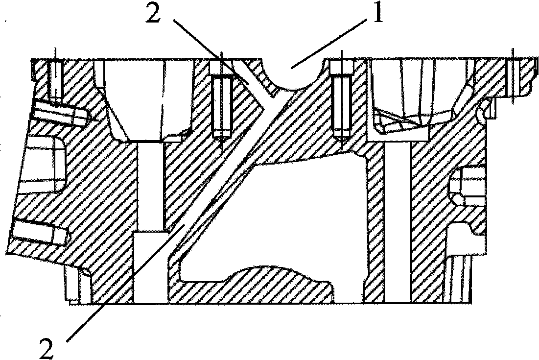
[0025] like figure 1 As shown, the cylinder head is provided with a main oil inlet passage 2 leading from the bottom of the cylinder head to the main journal hole of the camshaft and the middle position inside the camshaft bearing cap respectively. The oil passage in the main journal hole of the shaft and the oil passage that enters the inside of the camshaft bearing cap from the bottom of the cylinder head through the bolt hole in the middle of the cylinder head and the camshaft bearing cap. The main oil inlet passage 2 plays the role of supplying oil to the camshaft cover and lubricating the main journal hole of the camshaft.

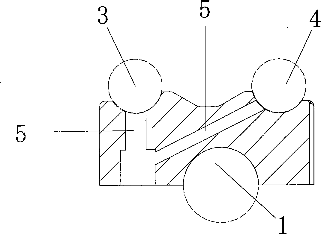
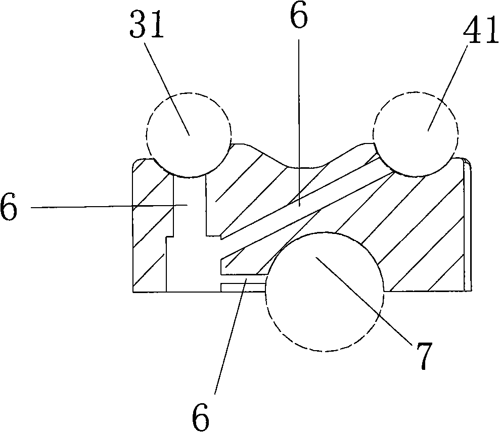
[0026] like figure 2 and image 3 As shown, the camshaft bearing cap is provided with a main oil passage 5 and a plurality of auxiliary oil passages 6, and the main oil passage 5 in the camshaft bearing cap leads to the air intake through the bolt hole in the middle position of the camshaft bearing cap. The oil passage in the central mounting hole...


PUM


Abstract

The invention aims at disclosing an engine with a novel oil line; the engine has simple structure and low cost, is lubricant and reliable and comprises an air cylinder cover, a bearing cover of a cam shaft which is fixed on the air cylinder cover by a positioning pin and a bolt, and a rocker shaft, a rocker, a hydraulic tappet and the cam shaft which are supported in the bearing cover of the cam shaft; particularly, the air cylinder cover is internally provided with a main oil-feeding pipeline which goes to a neck hole of a main shaft of the cam shaft and the middle position of the internal part of the bearing cover of the cam shaft from the air cylinder cover; the bearing cover of the cam shaft is internally provided with a main oil pipeline which is communicated with the main oil-feeding pipeline and the center installation hole of the rocker shaft, and multiple secondary oil pipelines which are communicated with the installation holes of the two sides of the rocker shaft and the neck hole of the secondary shaft of the cam shaft; the rocker shaft is internally provided with oil pipelines which are communicated with the center installation hole of the rocker shaft, the installation holes of the two sides and the installation holes of all the rockers; and the rocker is internally provided with the oil pipeline of the rocker which is communicated with the installation hole of the rocker and the internal part of the hydraulic tappet. The internal oil pipeline of the engine of the invention adopts the design of feeding the oil from the middle part, is easy to be processed and is lubricant and reliable.

Description

technical field [0001] The invention relates to an engine, specifically an overhead valve engine. Background technique [0002] The oil passage of the traditional overhead valve engine is to set a main oil passage through the engine cylinder head on the engine, through which the flow of lubricating oil is realized. The oil inlet hole of the main oil passage is set at one end of the cylinder head Such an engine has the following disadvantages: 1. Because the cylinder head is relatively long, it needs to be processed with a very long tool, so the requirements for the tool are high, the processing cost is high, and the processing technology of the main oil passage is complicated, which easily leads to the diameter of the holes at both ends. Inconsistent, it is difficult to ensure the balance of oil pressure at both ends; 2. The oil inlet is set at one end of the cylinder head, resulting in low oil pressure at the rear end of the oil circuit, and the oil pressure at the end of t...

Claims


Application Information

Patent Timeline
Patent Type & Authority Applications(China)
IPC IPC(8): F01M9/10
CPCF01M11/02F01M9/10F01M9/101F01M9/104F01M9/105F01M9/107
Inventor 赵远征刘文军
Owner CHERY AUTOMOBILE CO LTD
Why Eureka
Try Eureka