Valve seat structure of self-decompression ball valve

A self-releasing, valve seat technology, applied in the valve seat field, can solve problems such as valve leakage, and achieve the effect of prolonging the service life, easy to use, and simple in structure

Inactive Publication Date: 2009-01-14
NEWAY VALVE SUZHOU
View PDF0 Cites 4 Cited by
  • Summary
  • Abstract
  • Description
  • Claims
  • Application Information

AI Technical Summary

Problems solved by technology

[0005] The purpose of the present invention is to provide a valve seat structure with pressure relief function, which can effectively eliminate the pressure generated by the medium on the valve seat and valve ball, and solve the disadvantage of easy valve leakage due to deformation of the valve seat and valve ball

Method used


Image

  • Valve seat structure of self-decompression ball valve
  • Valve seat structure of self-decompression ball valve
  • Valve seat structure of self-decompression ball valve

Examples


Embodiment 1

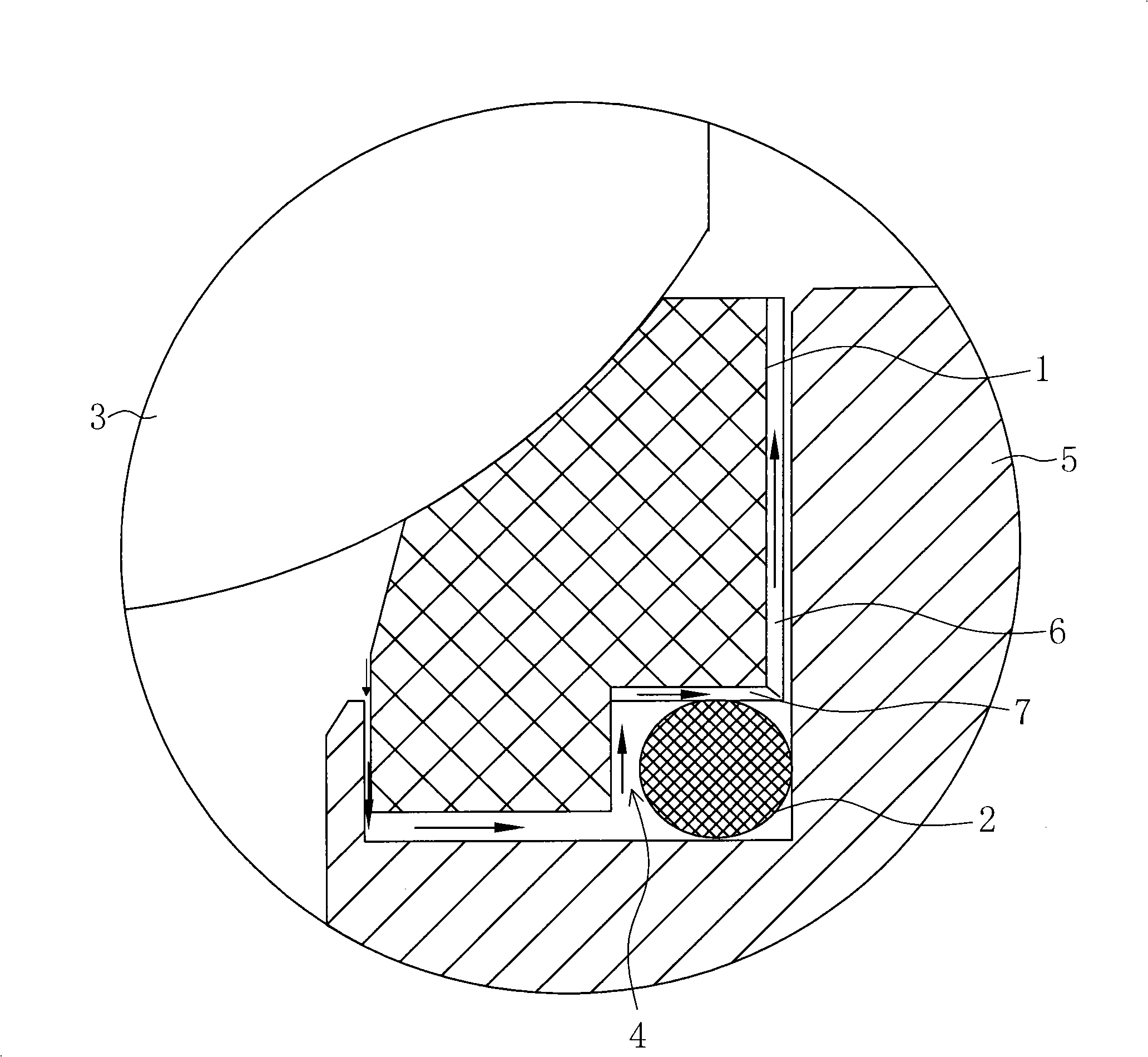
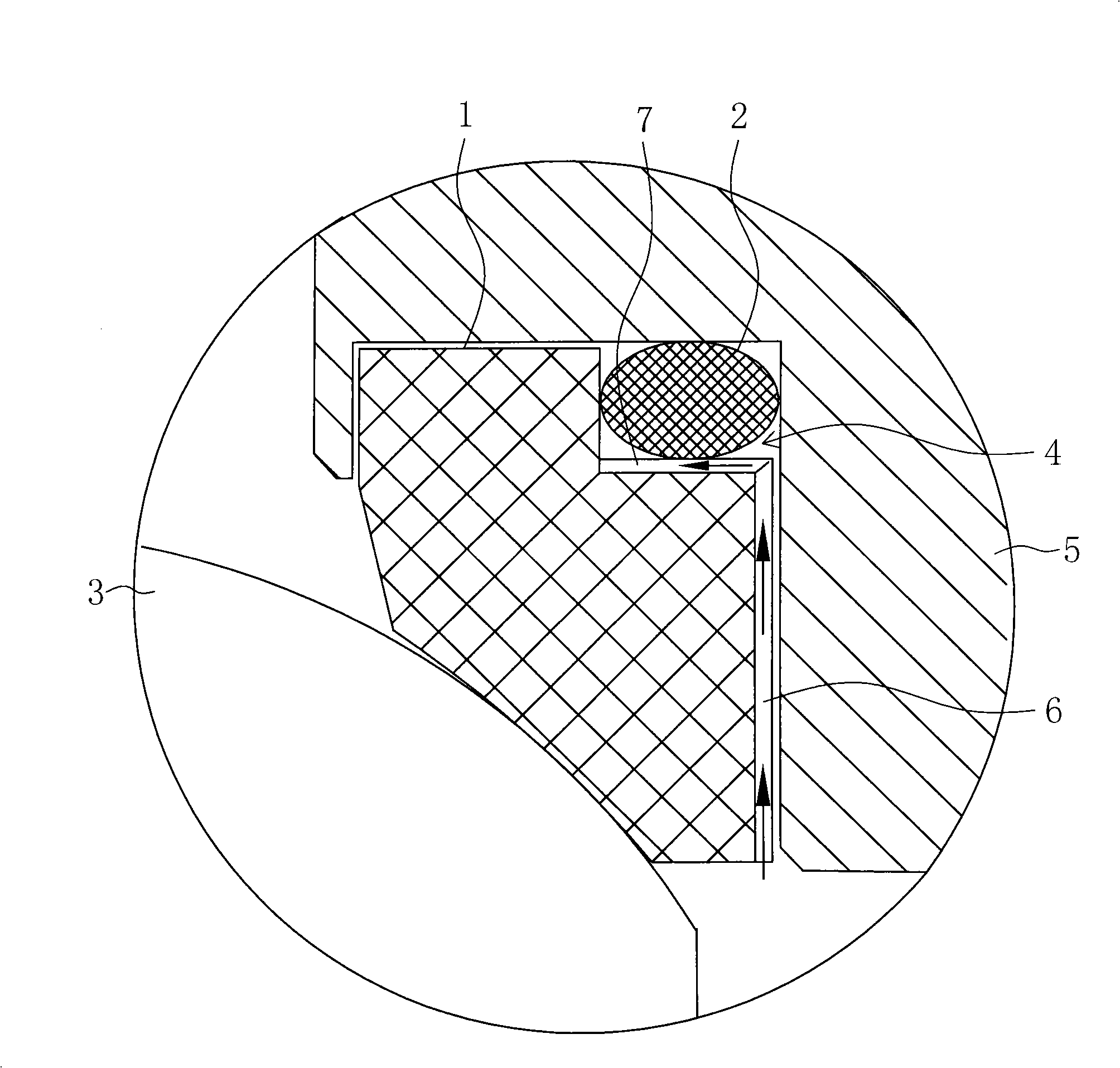
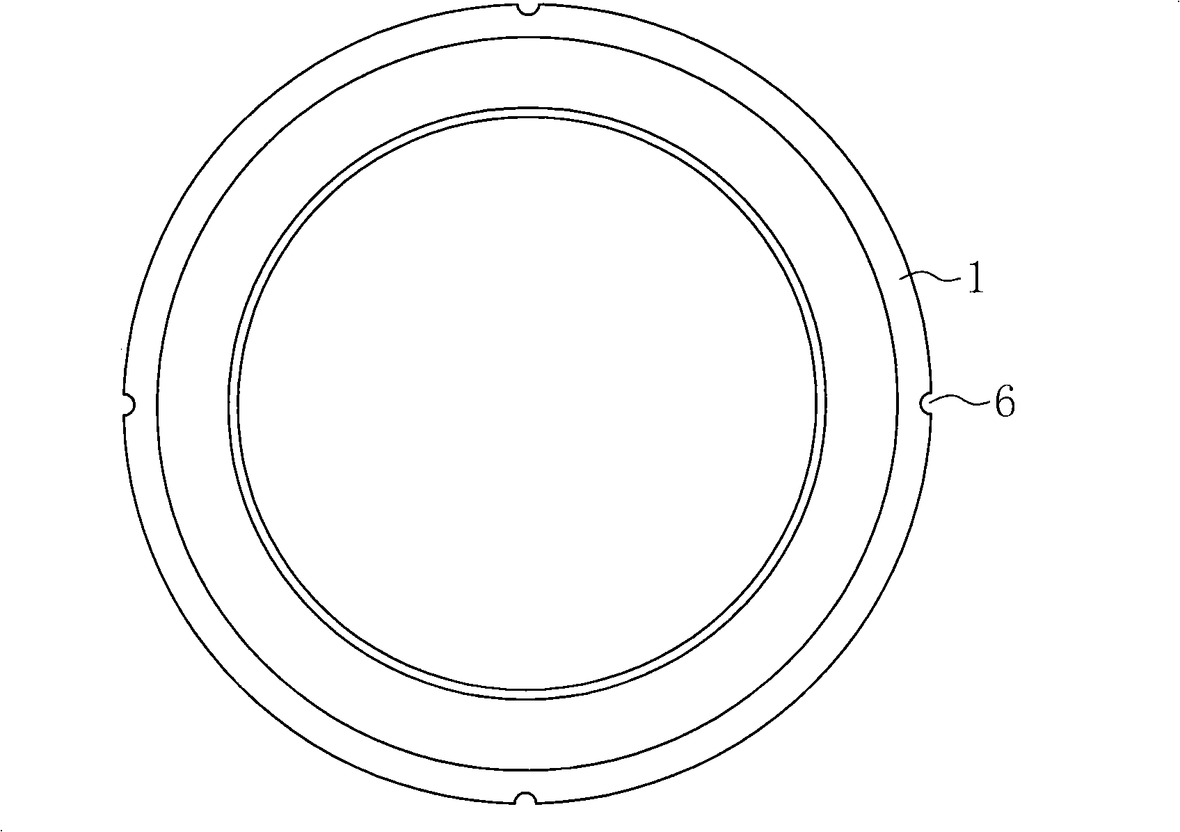
[0022] see Figure 1~4 As shown, a self-relieving ball valve seat structure includes a body 1, one side of the body 1 is bonded to the valve ball 3 to form a sealing surface, and the outer corner of the other side is provided with an annular gap 4, which is formed by cooperating with the valve cover 5 The ring channel that accommodates the O-ring 2, the outer wall of the valve seat 1 is provided with at least two pressure relief grooves 6 uniformly distributed in the circumferential direction, and the inner wall of the annular gap 4 adjacent to the outer wall of the valve seat is correspondingly provided with The pressure relief groove 6 communicates with another pressure relief groove 7 .

[0023] In the above, the direction of medium entry is from bottom to top, figure 1 The medium enters the inner cavity from the inlet end of the ball valve through the pressure relief groove, figure 2 The medium medium is sealed by the valve seat and O-ring at the outlet end and cannot b...

Embodiment 2

[0026] A self-relieving ball valve seat structure, including a body, one side of the body is bonded with the valve ball to form a sealing surface, and the outer corner of the other side is provided with an annular gap, which cooperates with the valve cover to form a ring for accommodating an O-ring. The outer wall of the valve seat is provided with at least two pressure relief grooves uniformly distributed in the circumferential direction, and another pressure relief groove communicating with the pressure relief groove is correspondingly provided on the inner wall of the annular gap adjacent to the outer wall of the valve seat .

[0027] In the above, the number of pressure relief grooves on the outer wall of the valve seat is 8 and arranged axially, and the number of pressure relief grooves on the inner wall of the annular notch is also 8 and arranged radially, and communicate with the pressure relief grooves respectively . This situation is suitable for the occasion of high...


PUM


Abstract

The invention discloses a valve seat structure of a pressure self-releasing ball valve, which comprises a body; one surface of the body is jointed with the valve ball to form a sealing surface, and the exterior angle part of the other surface thereof is provided with a ring-shaped gap which matches with a valve cover to form a ring channel which can hold an O-typed ring; the outer side wall of the valve seat is provided with at least two pressure releasing grooves which are distributed evenly along the peripheral direction; the inner wall of the ring-shaped gap which is adjacent to the outer side wall of the valve seat is accordingly provided with another pressure releasing groove which is communicated with the pressure releasing grooves. By opening the pressure releasing grooves in proper positions of the valve seat, the valve seat structure leads the media to enter the inner cavity of the valve body by the pressure releasing grooves although the valve gate is in a closed status, thereby realizing the pressure balance of the outer cavity and the inner cavity of the ball valve, overcoming the shortage that the valve gate is easy to release due to the valve seat and the valve ball deformation which is caused by the media pressure, and prolonging the service life.

Description

technical field [0001] The invention relates to a valve seat, in particular to a valve seat structure used on a self-relieving ball valve. Background technique [0002] In metallurgy, chemical industry, petroleum, food, medicine and other industries, ball valves are usually installed on hydraulic pipelines or fluid material delivery pipelines. Ball valves are widely used for their rapid opening and closing and good sealing performance. [0003] The basic structure of the existing ball valve is: a ball is set in the inner cavity of the valve body. When the valve is in the open state, the through hole in the middle of the ball communicates with the inlet and outlet at both ends of the valve cover, that is, the through hole constitutes a section of the pipeline. ;When closed, the upper valve stem drives the ball to rotate 90 degrees, so that the through hole and the center line of the pipeline are perpendicular to each other, and the pipeline is blocked by the smooth spherical...

Claims


Application Information

Patent Timeline
Patent Type & Authority Applications(China)
IPC IPC(8): F16K39/06F16K5/06
Inventor 訾松江
Owner NEWAY VALVE SUZHOU
Why Eureka
Try Eureka