Low friction face sealed reaction turbine rotors

a reaction turbine and sealing technology, applied in the field of rotary jetting tools, can solve the problems of increasing the cost and complexity of drilling, reducing the pressure and power available for jetting, and the torque produced by the working jet must be sufficient to overcome the static bearing, etc., to achieve low starting torque, reduce wear and torque, and reduce the effect of starting torqu

Active Publication Date: 2007-04-10
WELLS FARGO BANK NAT ASSOC +1
View PDF37 Cites 38 Cited by
  • Summary
  • Abstract
  • Description
  • Claims
  • Application Information

AI Technical Summary

Benefits of technology

[0011]The present invention is a reaction turbine rotor with axially-opposed pressure-balanced mechanical face seals. The rotor is capable of operating with low starting torque, consistent with the relatively low torque generated by the reaction forces of offset jets. The pressure-balanced design of the present invention limits the contact forces on the mechanical face seals, thereby reducing wear and torque. Also, the mechanical face seal surfaces are fabricated from ultra-hard materials, such as tungsten carbide, silicon carbide, and diamond, to minimize wear.

Problems solved by technology

Many designs for rotating jetting tools incorporate relatively small fluid passages, which reduce the pressure and power available for jetting.
Other systems require that the operating fluid used be filtered to a high degree, which adds significant expense and complexity.
The drawback to this configuration is that the torque produced by the working jets must be sufficient to overcome the static bearing and seal friction.
The dynamic friction of bearings and seals is typically lower than the static friction, so once the rotor has started to turn, it can spin at excessive speeds, which can cause overheating or bearing failure.
These bearings are subject to high loads and can fail when the rotor's rotational speed is excessive.
While journal bearings cannot support high thrust or radial loads, they are effective at high velocity—where the hydrodynamic support is greatest.
One drawback to this configuration is that the fluid settling chamber is small compared with the sealing diameter of the rotor.
The greatest drawback to the use of radial clearance seals is that clearance seals are prone to jamming with debris, especially when the operating pressure is applied slowly.
Particles approximately the same size or larger than the gap can easily get jammed in the gap and can build up during periods when fluid pressure is low and the rotor is not spinning.
In many applications, a relatively large volume of working fluid is required, and filtering the fluid becomes impractical.
If fluid is not flowing through the gap, debris cannot be carried into it.
Secondly, the sealing gap is not rigidly fixed, as in a radial clearance seal.
High pressure results in high contact forces between the seal faces, which can lead to premature failure and a high starting torque.
The need for separate thrust bearings complicates the tool design and increases the length of the jetting tool.
Secondly, the high-operating pressure imposes high contact loads on the seal faces, which results in a high starting torque.
This torque is relatively small and is generally insufficient to overcome the friction torque of a conventional mechanical face seal.
Finally, it may be desirable to operate rotating jetting tools at relatively high rotational speeds, resulting in a high pressure-velocity (PV) load on any conventional mechanical face seal included within the rotating jetting tool.
High PV values cause premature wear and failure of mechanical face seals.
For rotors used in rotating jetting systems for drilling and servicing oil and gas wells and production equipment, an external thrust bearing is impractical, and the thrust loads must be much lower than those induced by the working pressure multiplied by the effective seal area.

Method used


Image

  • Low friction face sealed reaction turbine rotors
  • Low friction face sealed reaction turbine rotors
  • Low friction face sealed reaction turbine rotors

Examples


Embodiment Construction

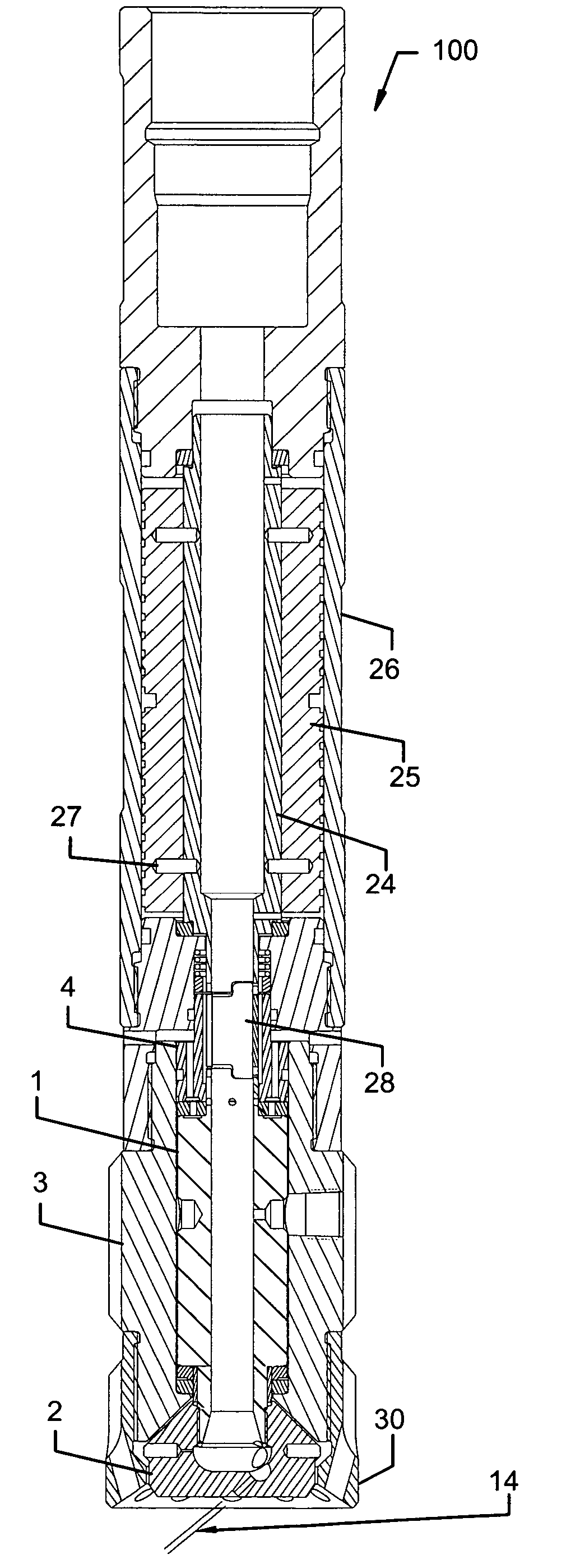
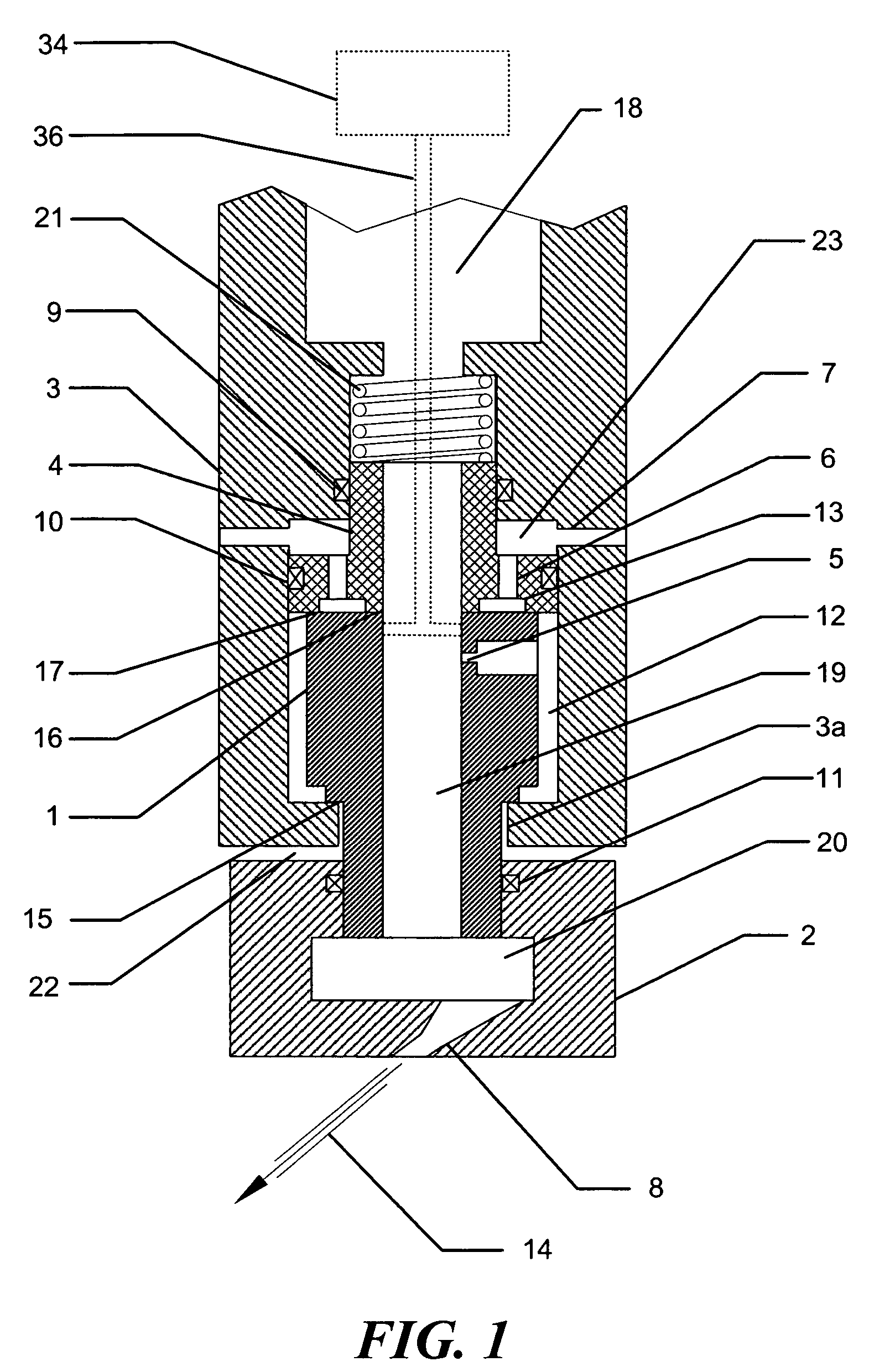
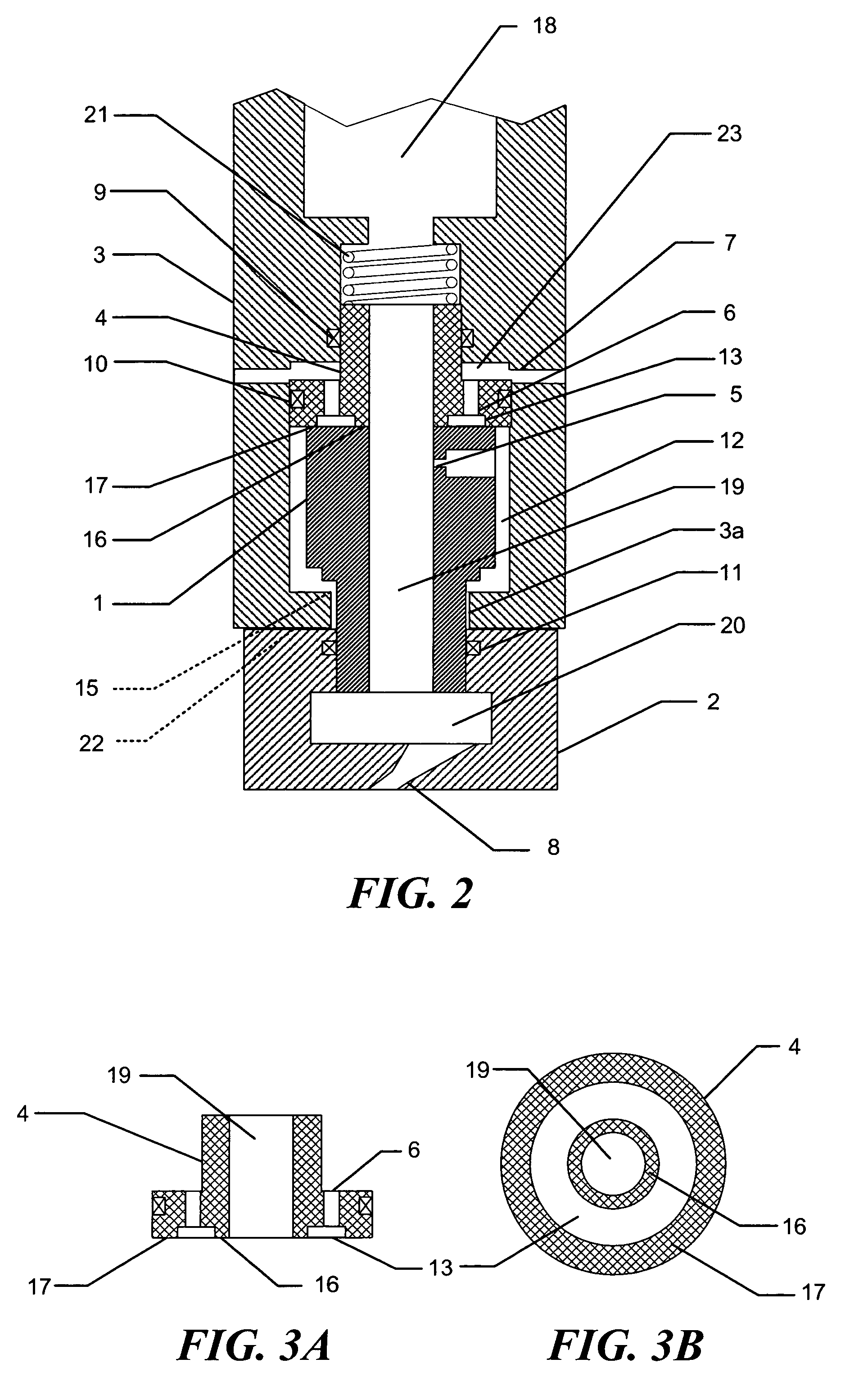
[0027]Referring to FIG. 1, a cross-sectional side view of a rotary jetting assembly in accord with the present invention is shown. The assembly includes four major components, including a rotor shaft 1, a nozzle head 2, a housing 3, and a seal head 4. Rotor shaft 1 and seal head 4 are disposed in housing 3, which includes a pressure chamber 12 (capable of withstanding the operating pressure of the system). Fluid enters at the top of housing 3 through an inlet passage 18, and is conveyed to pressure chamber 12 through an orifice 5, and to a reservoir 20 in a nozzle head 2 through a flow-through passage 19. While the present invention can be operated using a wide range of fluid pressures, normal operating pressures will range from about 3000 PSI to about 15,000 PSI. However, it should be understand that this range is exemplary, and is not intended to limit the present invention, since operating pressures as low as 1000 PSI and as high as 40,000 PSI are clearly possible. Nozzle head 2 ...


PUM


Abstract

Rotary jetting tool including a rotor with axially-opposed pressure-balanced mechanical face seals. Vented upper mechanical face seal enables the rotor to be operated with the relativity low starting torque achievable using reaction forces from offset jets energized with a pressurized fluid. When rotor is displaced axially due to set-down conditions, a pressure chamber exerts a pressure imbalance on the rotor, forcing the rotor to return to a normal operating position. Alternate structure to achieve low starting torque includes a volume disposed adjacent to a lower mechanical face seal, the volume being coupled in fluid communication with the pressurized fluid. Mechanical face seal surfaces are fabricated from ultra-hard materials, such as tungsten carbide, silicon carbide, and diamond. A gage ring designed to ensure the jets remove all of the material from the gage of the protective housing before the tool can advance can be incorporated.

Description

RELATED APPLICATIONS[0001]This application is based on a prior now abandoned provisional application Ser. No. 60 / 520,919, filed on Nov. 17, 2003, the benefit of the filing date of which is hereby claimed under 35 U.S.C. § 119(e).FIELD OF THE INVENTION[0002]This invention generally relates to rotary jetting tools for drilling and servicing oil and gas wells and production equipment, and more specifically, to a reaction turbine rotor with axially-opposed pressure-balanced mechanical face seals.BACKGROUND OF THE INVENTION[0003]There are a wide variety of applications where process or transport tubing becomes fouled with deposits or scale. Water jets, generated by a rotating jetting tool and directed across the internal surface of the tubing or pipe, are commonly used for cleaning these deposits. Such rotating jetting tools can also be used to drill through soil and rock formations. The jet quality provided by the rotating jetting tool is important, especially in harder formations. Jet ...

Claims


Application Information

Patent Timeline
Patent Type & Authority Patents(United States)
IPC IPC(8): E21B7/18B05B3/02E21B37/00
CPCB05B3/002B05B3/026B05B3/06E21B7/18E21B37/00
Inventor MARVIN, MARK H.KOLLE, JACK J.
Owner WELLS FARGO BANK NAT ASSOC
Why Eureka
Try Eureka