Wind power generation device

A technology for wind power generation devices and generators, applied to wind power generation, wind power engines, wind power motor combinations, etc., can solve the problems of high installation location requirements, limited application range, high wind direction requirements, etc., to improve power generation efficiency, wide application range, Good use of wind energy

Pending Publication Date: 2022-04-22
JIANGSU DEKEMA ELECTRIC
View PDF0 Cites 0 Cited by
  • Summary
  • Abstract
  • Description
  • Claims
  • Application Information

AI Technical Summary

Problems solved by technology

[0005] First, the requirements for wind speed and wind force are high. The larger the blades are, and the starting torque of the generator is larger, the higher the requirements for wind speed and wind force are. When the wind with low wind speed and wind force is small, the blades cannot be blown, and no electric energy will be generated. In this way, the power generation efficiency is low;
[0006] Second, the requirements for the installation location are high. Large-scale wind power generation devices can only be installed in areas with high wind speeds, such as seaside and mountain tops, which have geographical limitations;
[0007] 3. There is noise. Due to the large size of the wind rotor, blades, generator, etc., when they are turned, there is a lot of noise, which affects the surrounding residents;
[0008] Fourth, transportation, installation, and maintenance are inconvenient. Due to the large size of the wind wheel and blades, special equipment is required for transportation, installation, and maintenance;
[0009] Fifth, it occupies a large area. Due to the large size of the wind rotor and blades, for safety reasons, there are basically open spaces around large-scale wind power generation devices;
[0010] Sixth, the cost is high. Due to the large size of the wind rotor and blades, special large-scale mold production is required, and transportation, installation, and maintenance are inconvenient, so the production cost, installation cost, transportation cost, and maintenance cost are all high;
[0011] Seventh, the wind direction is high, and the large-scale wind power generation device cannot adjust the direction of the blades according to the wind direction. If the wind direction is wrong, the blades cannot rotate to generate electricity;
[0014] 10. The scope of application is limited, and it can only be used for power transmission to power stations for grid connection.

Method used


Image

  • Wind power generation device
  • Wind power generation device
  • Wind power generation device

Examples


Embodiment 1

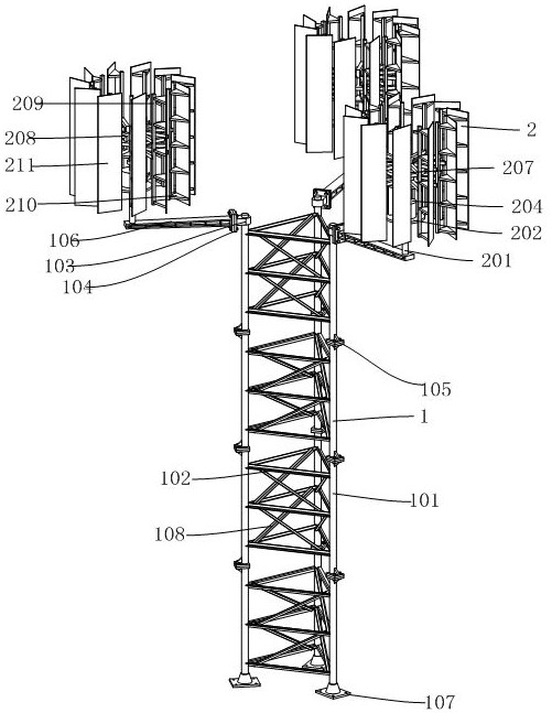
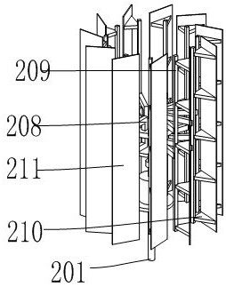
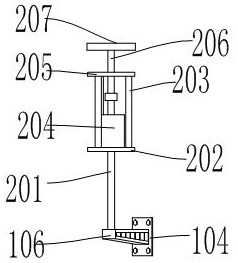
[0045] see Figure 1-Figure 4 , the present invention provides a wind power generation device, comprising a support mechanism 1 and three power generation mechanisms 2, the support mechanism 1 includes a column 101, a beam 102, and a support beam 106, the number of columns 101 is at least three and is evenly distributed in a triangle, three Each column 101 corresponds to three generators 2 respectively, and the beam 102 is horizontally fixed between the adjacent columns 101. Three support beams 106 are fixed on the top of the column 101. Each generator 2 includes a support rod 201, a generator support 202, Support column 203, generator 204, rotating shaft support 205, rotating shaft 206, support support 207, support 208, connecting rod 209, blade 211, support rod 201 is welded on one side of the top of support beam 106, and power generator is welded on the top of support rod 201. The machine support 202, the top surface of the generator support 202 is evenly welded with three ...

Embodiment 2

[0056] see Figure 5 , the second embodiment is basically the same as the first embodiment, the difference is that a central rod 109 is arranged between the three uprights 101, and a triangular plate 110 is fixed on the central rod 109, and the three ends of the triangular plate 110 are respectively fixed with three beams 102 , thus further improving the strength of the support mechanism 1 . A first reinforcement rod 111 is fixed between the beam 102 and the support beam 106, a second reinforcement rod 112 is fixed between the first reinforcement rod 111 and the support beam 106, and a third reinforcement rod 112 is fixed between the two second reinforcement rods 112. The rod 113 further improves the structural strength of the support beam 106 and the column 101, increases the stability, and prevents the generator mechanism 2 from shaking.

Embodiment 3

[0058] see Figure 6 The third embodiment is basically the same as the first embodiment, except that the shape of the blades 211 is arc-shaped, which increases the contact area with the wind, facilitates the rotation, and improves the power generation efficiency.


PUM


Abstract

The invention relates to a wind power generation device which comprises a supporting mechanism and three power generation mechanisms, the supporting mechanism comprises stand columns and the like, the number of the stand columns is at least three, the stand columns are evenly distributed in a triangular mode, the three stand columns correspond to the three power generation mechanisms respectively, a cross beam is horizontally fixed between the adjacent stand columns, and three supporting beams are fixed to the top ends of the stand columns. Each power generation mechanism comprises a supporting rod and the like, the supporting rod is welded to one side of the top end of the supporting beam, a generator support is welded to the top end of the supporting rod, three supporting columns are annularly and evenly welded to the portion, close to the outer side, of the top end face of the generator support, and rotating shaft supports welded to the three supporting columns are arranged on the top end faces of the supporting columns. A generator is installed on the top of the generator support and located on the inner side of the supporting column. The three power generation mechanisms are adopted, and a plurality of blades are adopted for driving rotation, so that wind energy can be better utilized.

Description

technical field [0001] The invention belongs to the field of generators, in particular to a wind power generator. Background technique [0002] As a clean energy, wind energy has been widely used in my country in recent decades. In the past forty years, the stand-alone capacity of wind power installations has increased approximately forty-fold. [0003] The working principle of the wind power generation device is relatively simple. The wind wheel rotates under the action of wind force, which converts the kinetic energy of the wind into the mechanical energy of the wind wheel shaft, and the generator rotates to generate electricity under the drive of the wind wheel shaft. Broadly speaking, wind energy is also solar energy, so it can also be said that a wind power generation device is a thermal energy utilization generator that uses the sun as a heat source and the atmosphere as a working medium. [0004] With the continuous increase in the size of wind rotors and blades, la...

Claims


Application Information

Patent Timeline
Patent Type & Authority Applications(China)
IPC IPC(8): F03D9/25F03D3/00F03D3/02F03D3/06F03D13/20
CPCF03D9/25F03D9/255F03D3/005F03D3/02F03D13/20F03D3/062Y02E10/74Y02E10/728Y02P70/50
Inventor 蔡志加
Owner JIANGSU DEKEMA ELECTRIC
Why Eureka
Try Eureka