integrated air supply unit

An air supply, air spring technology, applied to vehicle subunit functions, pump elements, components of pumping devices for elastic fluids, etc., can solve problems such as inability to cost-effectively manufacture, troublesome connections, etc., to improve diagnostic performance and fault protection performance, good on-time, long power effect

Active Publication Date: 2019-05-21
CONTINENTAL AUTOMOTIVE TECH GMBH
View PDF7 Cites 0 Cited by
  • Summary
  • Abstract
  • Description
  • Claims
  • Application Information

AI Technical Summary

Problems solved by technology

In this embodiment, the components have to be cumbersomely connected via additional lines, and these niche applications are therefore likewise not cost-effective to produce

Method used


Image

  • integrated air supply unit
  • integrated air supply unit
  • integrated air supply unit

Examples


Embodiment Construction

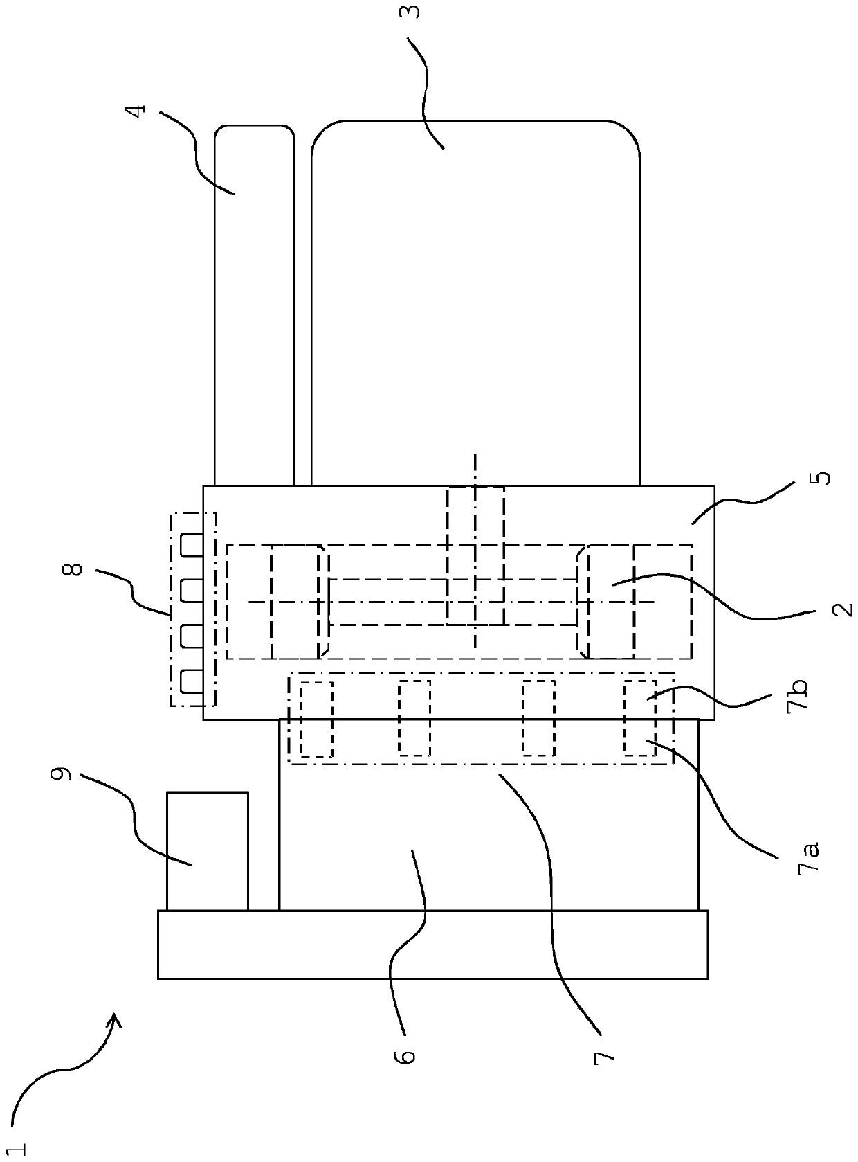
[0037] figure 1 An integrated air supply unit 1 for an air spring system of a motor vehicle is shown in a schematic diagram. Inside the pneumatic block 5 is shown an air compressor 2 driven by an electric motor 3 mounted at the front. In addition, an air dryer 4 is installed at the front.

[0038] The pneumatic block 5 has receptacles, not shown in detail, for individual components. A plurality of pneumatic valves 7 are schematically shown, which are arranged inside the pneumatic block 5 and are arranged adaptively to one another in the electronic controller 6 .

[0039] Integrated in the pneumatic block 5 is a drive unit 7 a of a pneumatic valve 7 comprising a valve core, a bush, an armature, a spring and a sealing seat. The solenoid valve coil 7 b of the pneumatic valve 7 is integrated in the electronic control unit 6 . The drive unit 7a and the solenoid valve coil 7b are fittingly connected to each other.

[0040] The pneumatic block 5 also includes channels, not shown, ...


PUM


Abstract

The invention relates to an integrated air supply unit (1), in particular for an air spring system of a motor vehicle, comprising an air compressor with a motor (3) and an air dryer (4) ( 2) wherein the air compressor (2) together with the motor (3), the air dryer (4) and the plurality of pneumatic connections (8) form a functional unit.

Description

technical field [0001] The invention relates to an integrated air supply unit, especially for an air spring system of a motor vehicle, said integrated air supply unit comprising an air compressor with a motor and an air dryer, wherein the air compressor is connected with the motor, the air The dryer and the pneumatic connections together form a functional unit. Background technique [0002] An air spring arrangement for a vehicle is known from document DE 10 2005 030 726 A1, which comprises the necessary components of current air spring systems. The air spring device has a compressor, an air dryer, a pressure accumulator, as well as various valves and compressed air lines. In addition, the gas spring system has a pressure sensor and is controlled by a controller. [0003] The main components of an air supply device for an air spring system according to the prior art include an air compressor, valves and a controller, which are usually installed in the vehicle in a manner d...

Claims


Application Information

Patent Timeline
Patent Type & Authority Patents(China)
IPC IPC(8): B60G17/015B60G17/052B60G17/056
CPCB60G17/0155B60G17/0523B60G17/056B60G2202/152B60G2500/201B60G2500/203B60G2600/66B60G2400/51222B60Y2400/306F04B27/005F04B27/04F04B35/04F04B53/10F04B53/16
Inventor J·博恩C·库尔斯U·福尔谢特C·沃斯M·齐德克D·海因A·欣茨C·维塔拉
Owner CONTINENTAL AUTOMOTIVE TECH GMBH
Why Eureka
Try Eureka