
Improved failure viewing apparatus and method

A technology for failing messages and tracking tasks. It is applied in digital transmission systems, data exchange networks, electrical components, etc. It can solve problems such as occupying a lot of memory, inconvenient fault location, and low efficiency, and achieve the effect of reducing message traffic.

Active Publication Date: 2009-01-14
ZTE CORP
View PDF0 Cites 2 Cited by
  • Summary
  • Abstract
  • Description
  • Claims
  • Application Information

AI Technical Summary

Problems solved by technology

In this way, too much manual intervention makes it difficult to locate the fault
[0004] In addition, the existing failure observation device supports multiple clients, and its working method is: if a failure occurs in the business, if it is found that there are currently multiple clients tracking, the system will send a message to all clients. Failure message, the result of this is that it was originally a failure message, because there are multiple clients tracking, resulting in the sending of multiple failure messages. Obviously, in the case of a relatively large amount of messages, this working method is very inefficient. and a waste of resources
[0005] To sum up, with the continuous improvement and development of the telecommunication system, different network elements or protocols will emerge one after another, which will inevitably lead to the limitations of the existing failure observation devices, That is: adopting the structure of the existing failure observation device, not only the implementation of the failure observation technology will be complicated, but also the maintenance cost of the device is relatively high, the repetitive workload is large, and manpower and resources are wasted
In addition, adopting the architecture of the existing failure observation device to implement the failure observation technology under the condition of large traffic, that is, a large amount of messages, it is bound to receive a large number of failure messages, often occupying too much memory, and the utilization rate of the CPU continues to be low. The situation seriously affects the performance of the device, and it is not convenient to locate the fault

Method used


Image

  • Improved failure viewing apparatus and method
  • Improved failure viewing apparatus and method
  • Improved failure viewing apparatus and method

Examples


Embodiment Construction

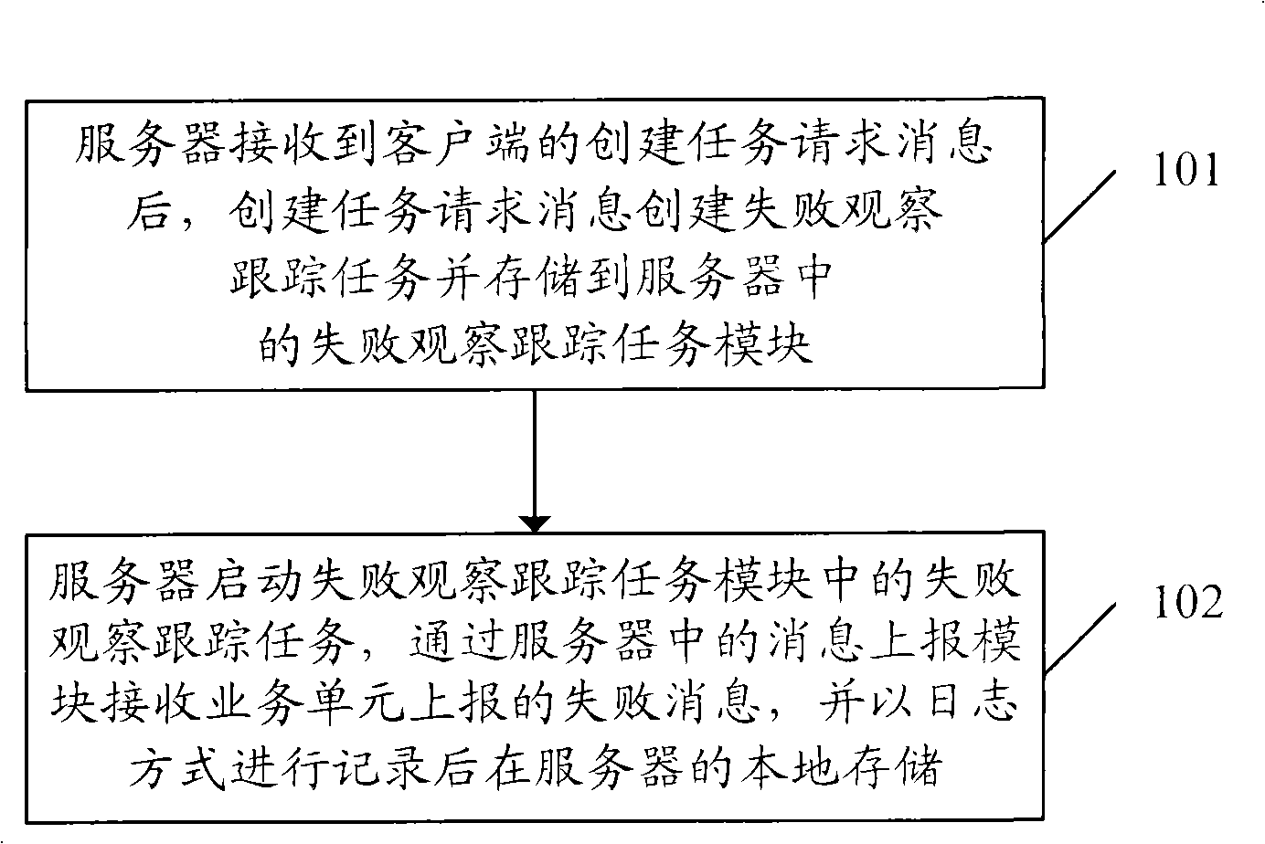
[0030] The core idea of ​​the present invention is: the failure observation and tracking task is pre-created by the server, that is, the business logic for realizing the failure observation technology is on the server side; Exists until the server is manually stopped. Moreover, the failure observation and tracking task corresponds to the reported failure message, and is used by the client to locate the reported failure message through the failure observation and tracking task, so as to locate the fault.

[0031] The implementation of the technical solution will be further described in detail below in conjunction with the accompanying drawings.

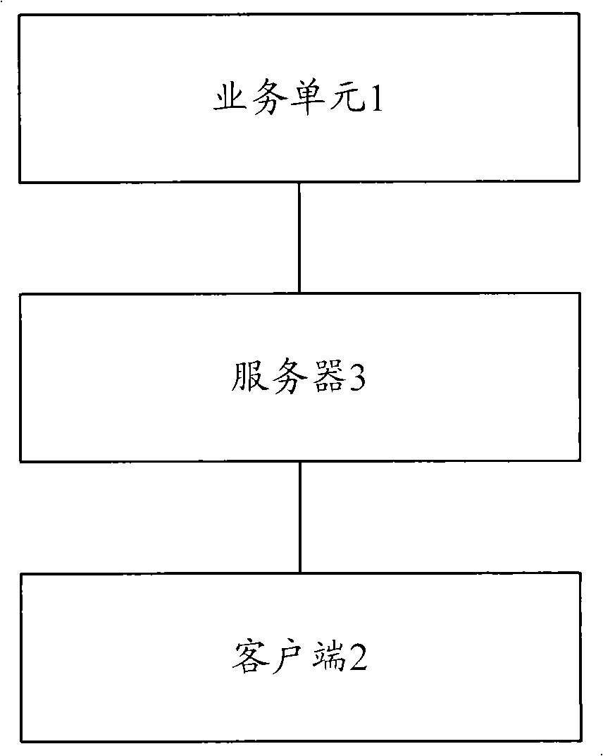
[0032] like figure 2As shown, an improved failure observation device includes: a business unit 1 and a client 2, and a server 3 is connected between the business unit 1 and the client 2. Wherein, the service unit 1 is existing, and will not be described in detail here. Only the client 2 and the server 3 are described below. To put...


PUM


Abstract

The invention discloses an improved failure finder, comprising a service unit, a client end and a server, wherein the server starts built failure finding and tracking task, receives failure information reported by the service unit and performs local storage on the server in a log mode after recording, and the stored failure information and the failure finding and tracking tack are corresponding. The invention also discloses an improved failure finding method, comprising: starting the built failure finding and tracking task by the server, receiving the failure information reported by the service unit through an information reporting module, and performing local storage on the server in a log mode after recording, wherein the stored failure information and the failure finding and tracking tack are corresponding. According to the device and the method of the invention, failure finding technology is simply realized, thereby being capable of positioning problem failure.

Description

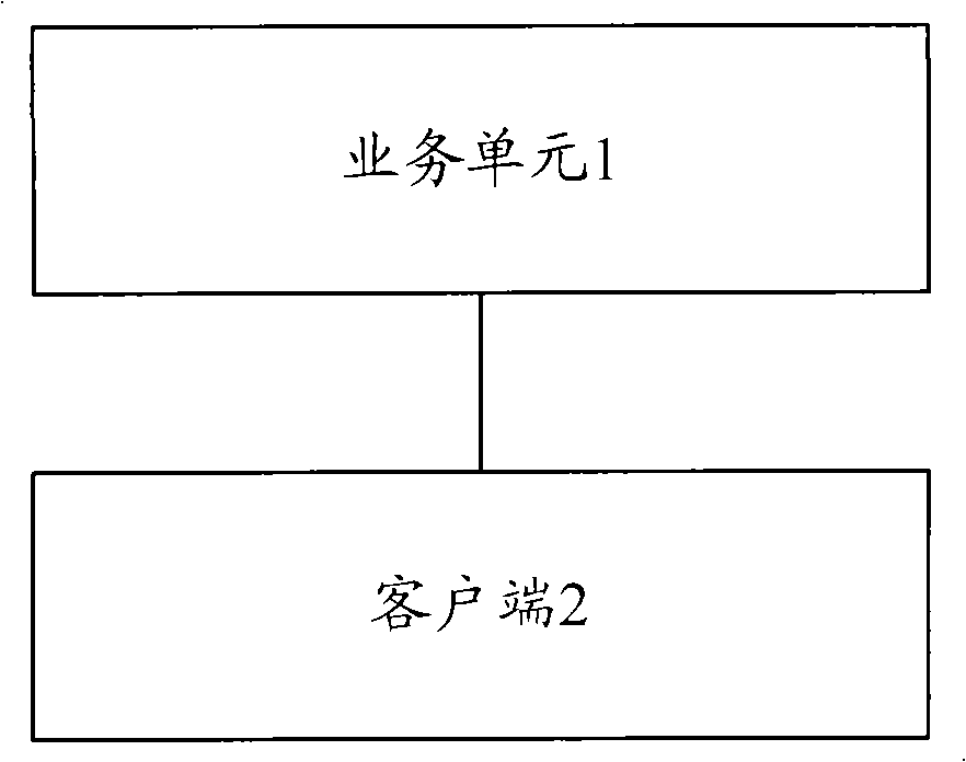
technical field [0001] The invention relates to a failure observation technology in a network management system, in particular to an improved failure observation device and method in the network management system. Background technique [0002] The architecture of existing failure observation devices is as follows: figure 1 As shown, it includes the business unit 1 in the foreground and the client 2 in the background. In practical application, there may be multiple business units, which are used to realize the business functions of different network elements or protocols; there may also be multiple clients, and the business logic for realizing the failure observation technology is located in the client 2 . The failure observation technology is a very important part of the network management system, and it is mainly used in the debugging, deployment and fault location of the network management system. For example, the business logic of the failure observation technology moni...

Claims


Application Information

Patent Timeline
IPC IPC(8): H04L12/24H04L12/26H04L29/06
Inventor 王亮
Owner ZTE CORP
Learn More