Radio transmitter, radio communication system, and radio transmission method
A wireless transmitter and wireless receiver technology, applied in wireless communication, radio transmission system, diversity/multi-antenna system, etc., can solve the problem of not being able to improve communication quality
- Summary
- Abstract
- Description
- Claims
- Application Information
AI Technical Summary
Problems solved by technology
Method used
Image

Examples
Embodiment approach 1
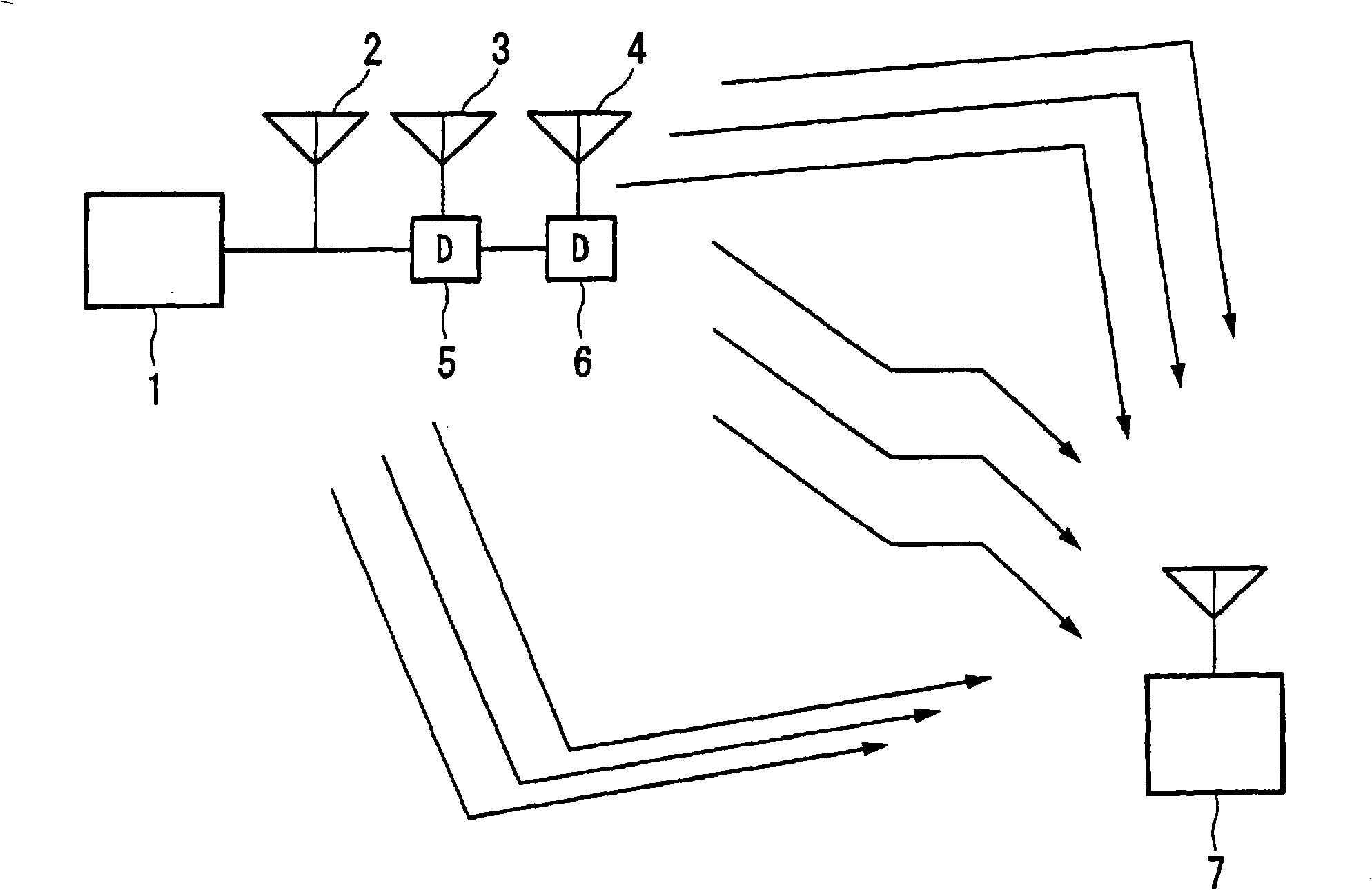
[0109] figure 1 It is a diagram for explaining a method of transmitting a signal from a wireless transmitter to a wireless receiver according to Embodiment 1 of the present invention. The signal sent by the wireless transmitter 1 reaches the wireless receiver 7 through a plurality of transmission paths. The wireless transmitter 1 has a plurality of transmitting antennas 2-4.
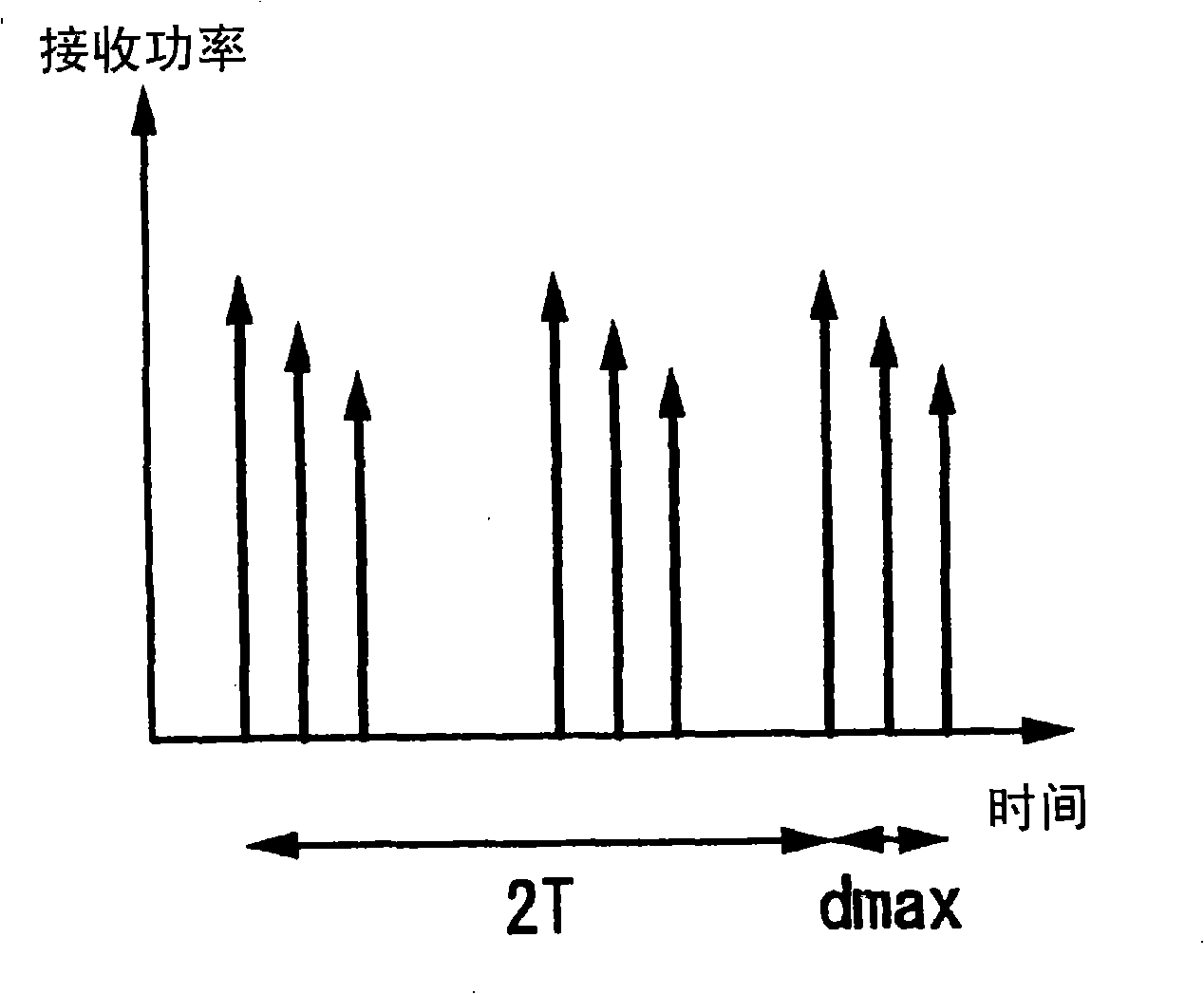
[0110] The delay unit 5 provides a delay time of T to the signal transmitted from the transmitting antenna 3 with respect to the signal transmitted from the transmitting antenna 2 . Furthermore, the delay units 5 and 6 give a delay time of 2T to the signal transmitted from the transmission antenna 4 .
[0111] The wireless receiver 7 receives the signal transmitted from the wireless transmitter 1 . In addition, in figure 1 In the above, a case where the transmitter 1 includes three transmitting antennas 2 to 4 is described as an example, but the number of transmitting antennas is not limited to thi...
Embodiment approach 2
[0145] FIG.12 is a block diagram showing the configuration of a base station apparatus according to Embodiment 2 of the present invention.
[0146] The base station apparatus has a PDCP (Packet Data Convergence Protocol) section 15, acquires an IP (Internet Protocol) packet, compresses its header, etc., and transmits it to an RLC (RadioLink Control) section 16, and in order to transmit the data acquired from the RLC section 16 Create an IP packet format and restore its header. And, the data acquired from the PDCP unit 15 is sent to the MAC (Media Access Control) unit 17 , and the data from the MAC unit 17 is sent to the PDCP unit 15 through the RLC unit 16 .
[0147] Furthermore, the MAC unit 17 executes ARQ (Automatic Repeat Request) processing, scheduling processing, data combination / disassembly, and control of the physical layer unit 18, transfers the data received from the RLC 16 to the physical layer unit 18, and transfers data from the physical layer unit 18 to the physi...
Embodiment approach 3
[0194] Description of this embodiment Figure 16 , Figure 17 , Figure 18 The case where the grouping of chunks is different from that shown in .
[0195] The structure of the base station apparatus is as shown in Fig. 12 and Figure 13 , as shown in FIG. 15 , and description thereof will be omitted in this embodiment. Also, as in Embodiment 2, chunks are assigned to terminals based on information included in CQI from terminals.
[0196] Here, it is the same as Embodiment 2, such as Figure 9As shown, a case where the base station apparatus 11 communicates with the terminals 12, 13, and 14 will be described.
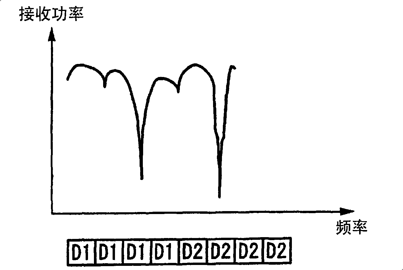
[0197] Figure 21 (a) is a diagram showing the transfer function C11 observed in the multi-user diversity area. and, Figure 21 (b) is a graph showing the transfer function C12 observed in the frequency diversity region. exist Figure 21 In (a) and (b), the horizontal axis represents frequency, and the vertical axis represents received power. exist Figure 2...
PUM
 Abstract
Description
Claims
Application Information