
Four-cylinder spherical internal combustion engine main body mechanism

An internal combustion engine, spherical technology, applied in the direction of internal combustion piston engines, combustion engines, machines/engines, etc., can solve the problems of high sealing and lubrication conditions, not widely used, difficult processing and control, etc., to achieve the elimination of piston straight lines Reciprocating motion, broad market application prospects, simple structure effect

Inactive Publication Date: 2009-01-21
吴银明
View PDF0 Cites 4 Cited by
  • Summary
  • Abstract
  • Description
  • Claims
  • Application Information

AI Technical Summary

Problems solved by technology

Since the crankshaft has a dead point when it is doing circular motion, and the reciprocating linear motion of the piston has a great impact, it is necessary to arrange multiple cylinders to work at the same time, resulting in complex motion mechanisms, many parts, and very difficult processing and control. Low utilization and low engine efficiency
For triangular rotor engines, since the sealing pins in contact between the triangular rotor and the bottom surface of the cylinder are double-sided contact working surfaces, the sealing work is poor, and the requirements for sealing and lubrication conditions are very high, and the requirements for materials are also very strict. At the same time, the inner surface of the cylinder and the triangular The outer surface of the rotor is a special special-shaped curved surface, and the main shaft uses gear wires to output power, which is extremely difficult to process and has not been widely used so far.

Method used


Image

  • Four-cylinder spherical internal combustion engine main body mechanism
  • Four-cylinder spherical internal combustion engine main body mechanism
  • Four-cylinder spherical internal combustion engine main body mechanism

Examples


Embodiment Construction

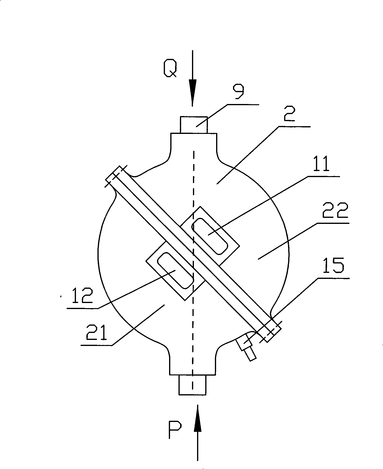
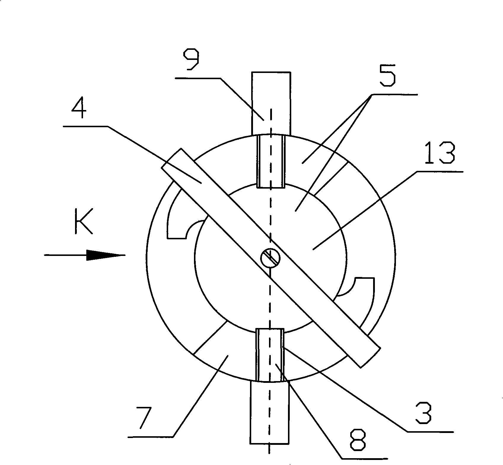
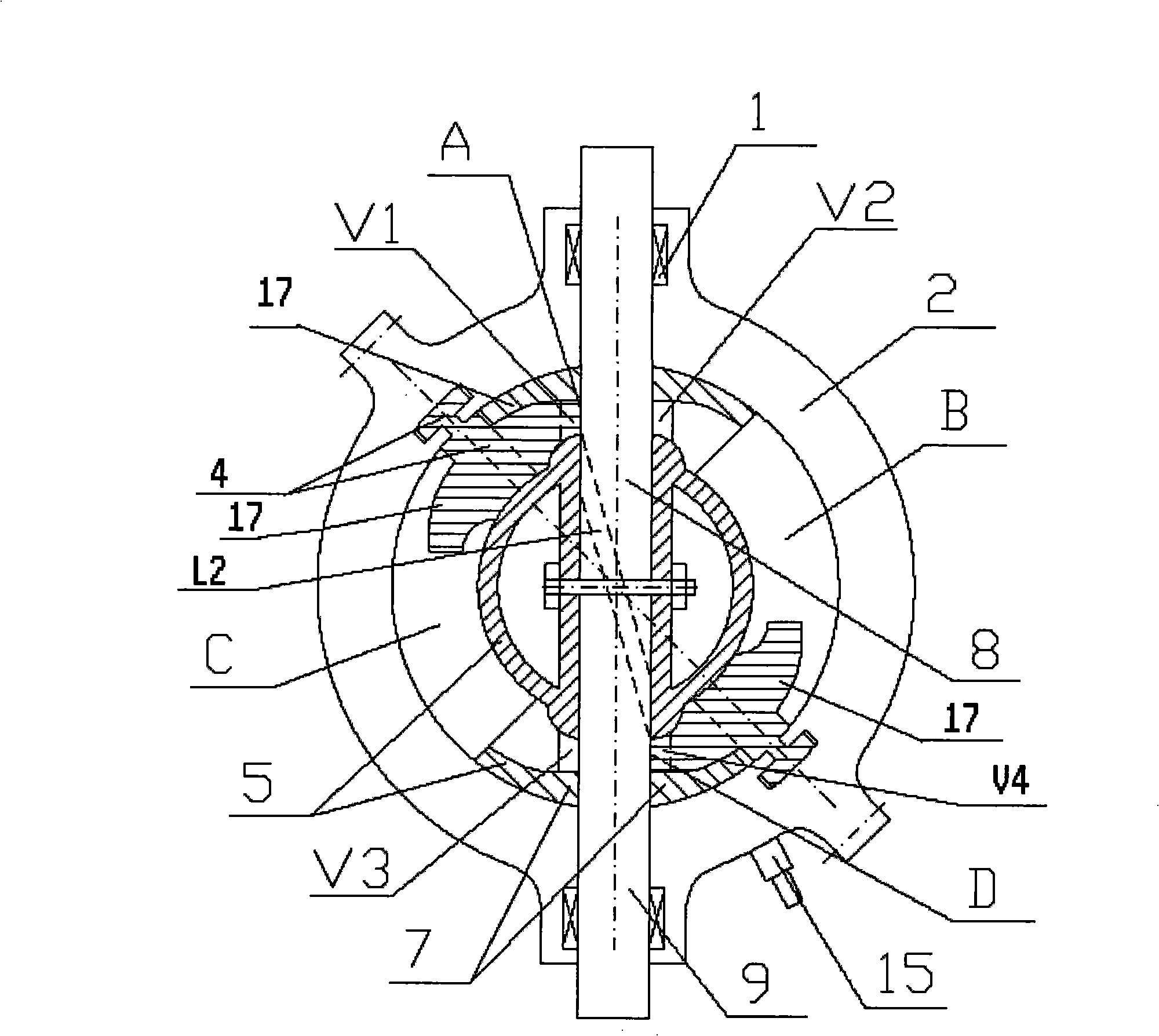
[0016] The main mechanism of the four-cylinder spherical internal combustion engine of the present invention includes a spherical casing 2 with main journal bearing seats 1 at both ends. In this embodiment, the spherical casing 2 is composed of a left half casing 21 and a right half casing 22 , the spherical casing 2 is provided with a septum ring 4 which forms an angle of 35 to 55 degrees with the center through holes of the main journal bearing seats 1 at both ends and can rotate relative to the spherical casing 2. The septum ring 4 4 The middle part of the body is provided with a spherical-like rotating piston 5 with a spherical top surface 13 on the upper and lower parts. The two sides of the rotating piston 5 are symmetrically connected with piston petals 7 with a spherical surface on the outer surface, so that the air chambers on both sides of the septum ring 4 form four working air chambers A, B, C, and D. The spherical casing 2. The upper or lower part corresponds to t...


PUM


Abstract

The invention relates to a main mechanism for a four-cylinder spherical internal combustion engine, comprising a spherical casing having two ends provided with bearing seats. A partition circular ring which has an angle between 35 and 55 degrees with a connecting line of center through holes of the bearing seats at two ends is arranged inside the spherical casing; the upper or lower part of the spherical casing is provided with an air inlet and an exhaust port corresponding to two sides of a partition rotary plate; the middle part inside the partition rotary plate body is provided with a spherical-like rotary piston; two end parts of the axial lead of the rotary piston body are hinged with the partition rotary plate; two sides of the rotary piston are symmetrically connected with piston petal sheets, so as to ensure that air cavities positioned on two sides of the partition rotary plate form four working air chambers; a built-in circular rotary plate is arranged in a seam mouth on the middle part of the rotary piston; two ends of the built-in circular rotary plate are fixed with a main journal running through a bearing seat hole of the casing; two air ducts are symmetrically arranged on the built-in circular rotary plate; the piston petal sheets are respectively provided with through holes of four air ducts corresponding to the four working air chambers; and a spark plug extending into the spherical casing is arranged on the spherical casing. The main mechanism not only can be used for manufacturing an internal combustion engine with a new working form, but also is compact in structure and few in parts.

Description

technical field [0001] The invention relates to the field of internal combustion engines, in particular to a main body mechanism of a four-cylinder spherical internal combustion engine. Background technique [0002] At present, the widely used engine uses the reciprocating linear motion of the piston to compress the combustible gas, and then ignites the gas to generate a large amount of heat energy in an instant. By pushing the piston, the heat energy is converted into mechanical energy, and then the crankshaft is used to output torque. Since the crankshaft has a dead point when it is doing circular motion, and the reciprocating linear motion of the piston has a great impact, it is necessary to arrange multiple cylinders to work at the same time, resulting in complex motion mechanisms, many parts, and very difficult processing and control. The utilization rate is low, and the engine efficiency is also low. For triangular rotor engines, since the sealing pins in contact betw...

Claims


Application Information

Patent Timeline
Patent Type & Authority Applications(China)
IPC IPC(8): F02B53/02F02B55/08F02B55/02F01C1/00
CPCY02T10/17Y02T10/12
Inventor 吴银明
Owner 吴银明
Learn More