Encapsulation method of minitype flat plate hot pipe

A flat plate heat pipe and packaging method technology, applied in indirect heat exchangers, lighting and heating equipment, metal processing equipment, etc., can solve the problems of high processing difficulty and high equipment cost

Inactive Publication Date: 2009-01-21
HARBIN INST OF TECH
View PDF0 Cites 13 Cited by
  • Summary
  • Abstract
  • Description
  • Claims
  • Application Information

AI Technical Summary

Problems solved by technology

The advantage of this kind of process is that the bonding is firm and the sealing i...

Method used


Image

  • Encapsulation method of minitype flat plate hot pipe
  • Encapsulation method of minitype flat plate hot pipe
  • Encapsulation method of minitype flat plate hot pipe

Examples


Embodiment Construction

[0020] The present invention will be further described below in conjunction with accompanying drawing and specific embodiment:

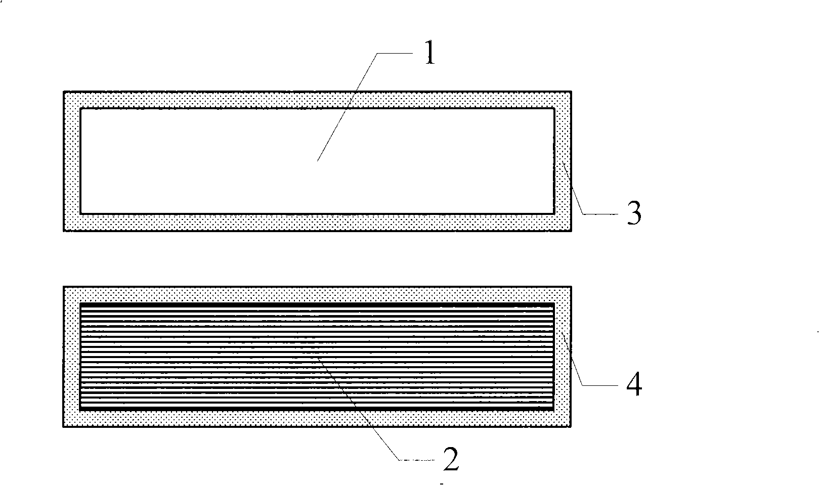
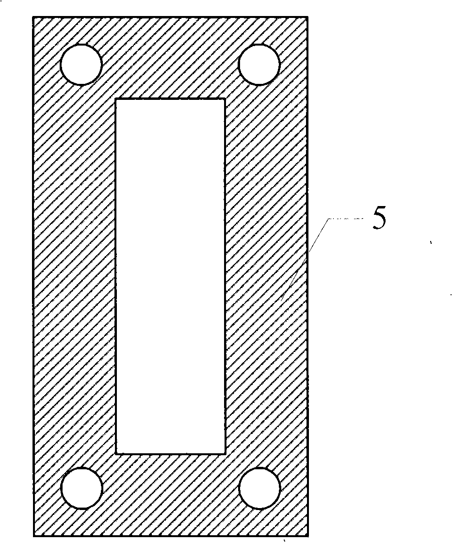
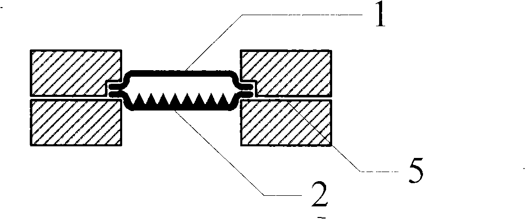
[0021] combine Figure 1-Figure 3 , the specific operation process of the encapsulation method in this embodiment is as follows:

[0022] At the beginning, use sandpaper to lightly polish the welding surfaces of the upper substrate 1 of the micro-plate heat pipe and the lower substrate 2 of the micro-plate heat pipe. force.

[0023] Then thoroughly clean the upper and lower substrates, and after drying, apply flux evenly on the upper and lower substrate welding strips 3 and 4 of the upper and lower substrates, in order to improve the wettability of the melted solder and the welding strips, so that they can be uniform and smooth plated on the solder strip.

[0024] Use a heater (electric soldering iron is used in this embodiment) to heat the solder and the upper and lower substrates at the same time to melt the solder, and apply the melted solder e...


PUM

PropertyMeasurementUnit
Widthaaaaaaaaaa

Abstract

The invention provides a packaging process for a mini-size flat heat pipe, wherein the upper basal plate and the lower basal plate of the mini-size heat pipe are made of metal, a ring welding belt is respectively produced on the peripheries of the upper basal plate and the lower basal plate, solder is plated on the welding belt, and the upper basal plate and the lower basal plate are calibrated to tighten by holding fixtures, and are heated up to smelt down solder, and are tightly connected through the solder after the solder is cooled, thereby forming the packaging of a flat micro-thermal pipe. The invention utilizes metal with low melting point as solder, and forces a certain pressure for the shell of the micro-thermal pipe through a special die, heats and smelts solder metal under the condition of vacuum or protective gas, and facilitates the upper basal plate and the lower basal plate of the mini-size flat heat pipe to adhere after the solder is cooled down, thereby realizing the packaging purpose of the micro-thermal tube. The invention has the advantages of convenient and reliable operation, simplification and flexibility, low cost and wide application.

Description

(1) Technical field [0001] The invention belongs to a packaging technology for heat pipes, in particular to a packaging method for miniature flat heat pipes. (2) Background technology [0002] The heat pipe is a high-efficiency heat transfer element. It uses the phase change of the working medium in the closed tube to conduct heat conduction, and can transmit a large amount of heat through a small cross-sectional area for a long distance without external power. The heat pipe principle was first proposed by Gaugler in 1944, but it was not adopted at that time. Until 1963, Grover of the Los Alamos National Laboratory in the United States independently re-invented a heat transfer element similar to that proposed by Gauglcr, and officially named this heat transfer element the heat pipe "Heat Pipe", pointing out that its thermal conductivity has exceeded any other. A known metal, and the experimental results of a heat pipe with sodium as the working medium, stainless steel as th...

Claims


Application Information

Patent Timeline
IPC IPC(8): F28D15/02B23K1/00
CPCF28D15/0233
Inventor 刘晓为韩天王喜莲王超
Owner HARBIN INST OF TECH
Why Eureka
Try Eureka