Eureka AIR delivers breakthrough ideas for toughest innovation challenges, trusted by R&D personnel around the world.

Frame of heat exchanger

A technology of heat exchangers and tube heat exchangers, which is applied in the field of serpentine tube heat exchangers and can solve problems such as distortion

Inactive Publication Date: 2009-01-21
THE BABCOCK & WILCOX CO
View PDF3 Cites 9 Cited by
  • Summary
  • Abstract
  • Description
  • Claims
  • Application Information

AI Technical Summary

Problems solved by technology

Welded connections are also known to limit the thermal expansion and contraction of the piping system, causing it to twist and sag, thus forming depressions in the horizontal extension of the piping system

Method used


Image

  • Frame of heat exchanger
  • Frame of heat exchanger
  • Frame of heat exchanger

Examples


Embodiment Construction

[0017] In the following, reference is made to the corresponding drawings, wherein like reference numerals designate like elements throughout the different drawings.

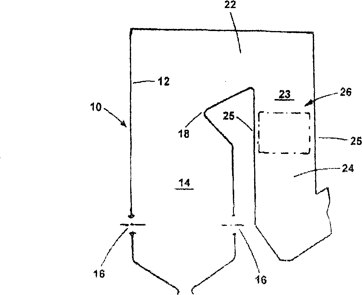
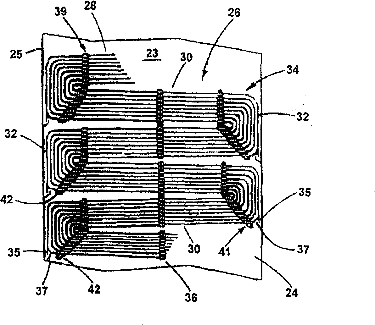
[0018] refer to figure 1 , figure 1 Shown is a steam generator 10 comprising water-cooled tube walls 12 defining a furnace cavity or combustion space 14 to which a fuel and air mixture is provided by a burner as indicated at 16 . After the combustion in the furnace chamber 14 is completed, the hot gas flows upwards and near the convex portion 18 of the furnace chamber, then crosses the horizontal portion 22 of the convection channel 23, and from there passes down the vertical portion 24 of the convection channel 23, vertically Section 24 is delimited by walls 25 and includes a heat exchanger such as a main superheater 26 . Typically, the gas leaving the vertical portion 24 of the convection channel 23 flows through a not shown air heater, from there through a not shown gas cleaning system, and then is discharge...


PUM


Abstract

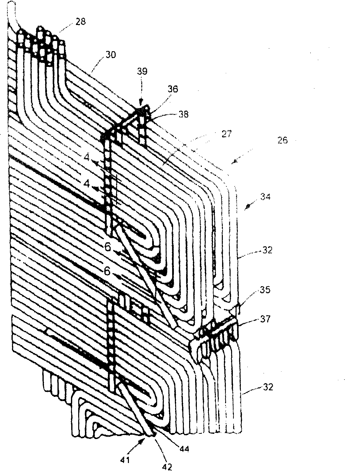
A structure frame is used to support a heat exchanger of a steam generator, wherein a heat exchanger is formed by coil pipes, and the coil pipe is provided with a sloping portion, therefore water can be easily exhausted out from the heat exchanger when the steam generator is shut down. The structure frame comprises pairs of first support groups which are perpendicularly and obliquely extended, and the first support group is closely straddled on the sloping portions, and pairs of first supports are rigidly connected with second supports which are extended among adjacent sloping portions. The structure frame keeps the sloping portions in intervals, prevents the direct contact between the adjacent pipe surfaces, and is not attached on the straddled pipe portion, thereby providing the enough loose pipe support engagement, and permitting the free movement of the pipes generated by the different expansion and shrinkage rate of the structure frame.

Description

technical field [0001] In general, the present invention relates to serpentine tube heat exchangers located in vertical gas passages of steam generators, and more particularly to the structure and support of the serpentine-oriented tubes so that when the steam generator is shut down, the serpentine Drainage of fluid collected in the guide tube. Background technique [0002] The heat exchange surface of the steam generator is arranged in the form of serpentine metal tube rows closely spaced from each other, and the metal tube rows are arranged in vertical channels through which the combustion gas is transmitted at a relatively high speed, in each row The metal tubes have horizontal extensions for conveying the fluid to be heated and are arranged in spaced apart parallel rows transverse to the direction of gas flow, a common example in the design of modern high capacity steam generators. [0003] Whenever the steam generator is shut down, water collects along the horizontal e...

Claims


Application Information

Patent Timeline
Patent Type & Authority Applications(China)
IPC IPC(8): F28F9/013F28F19/00F28D7/10F28D7/08
Inventor G·H·哈斯
Owner THE BABCOCK & WILCOX CO
Why Eureka
Eureka Blog
Learn More