Protection switching method, system and equipment based on Ethernet passive optical network

A passive optical network and protection switching technology, applied in the field of communication, can solve the problems of not being suitable for practical application, not suitable for upper-layer software expansion, and not considering the point-to-multipoint structure of EPON network, so as to achieve enhanced stability and practicability Effect

Inactive Publication Date: 2009-01-21
SUZHOU YUDESHUI ELECTRIC TECH CO LTD
View PDF0 Cites 25 Cited by
  • Summary
  • Abstract
  • Description
  • Claims
  • Application Information

AI Technical Summary

Problems solved by technology

[0017] In the process of realizing the present invention, the inventor found that the above method utilizes the reserved field of the multipoint control protocol data unit MPCPDU operation code to define the PST frame to realize protection switching, and the MPCP protocol is realized by the PON chip hardware, so the PST frame needs to be extended , requires chip support, not suitable for upper-layer software expansion
In addition, the protection switching in the above method does not consider the point-to-multipoint structure of the EPON network. When the trunk fiber and the branch fiber fail respectively, the same processing method will be adopted, which is not suitable for practical applications.

Method used


Image

  • Protection switching method, system and equipment based on Ethernet passive optical network
  • Protection switching method, system and equipment based on Ethernet passive optical network
  • Protection switching method, system and equipment based on Ethernet passive optical network

Examples


Embodiment 1

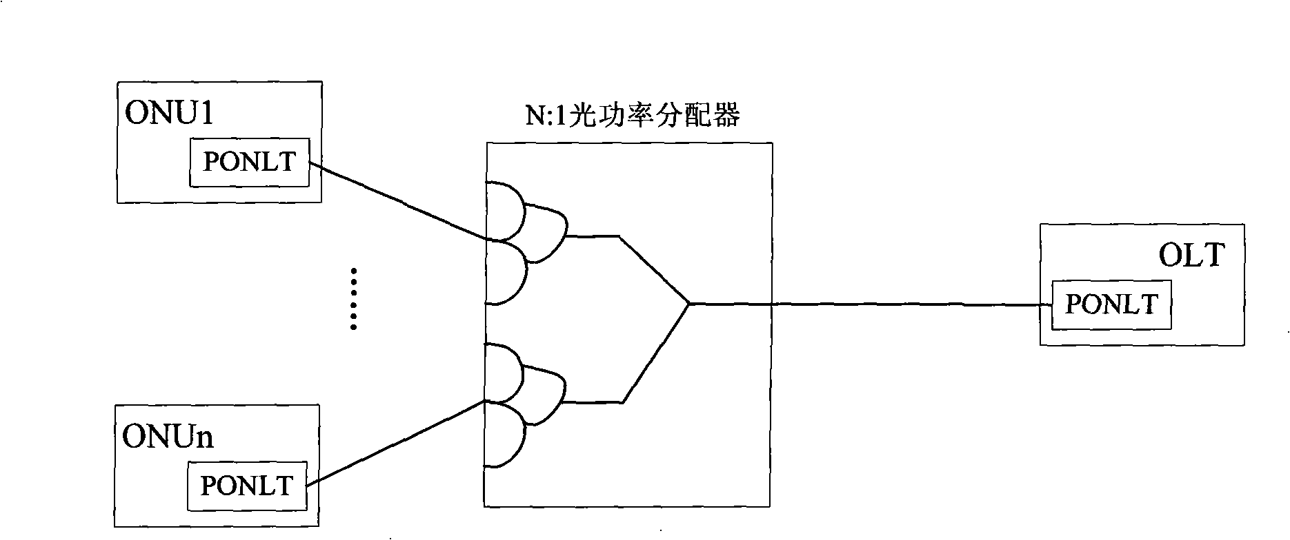
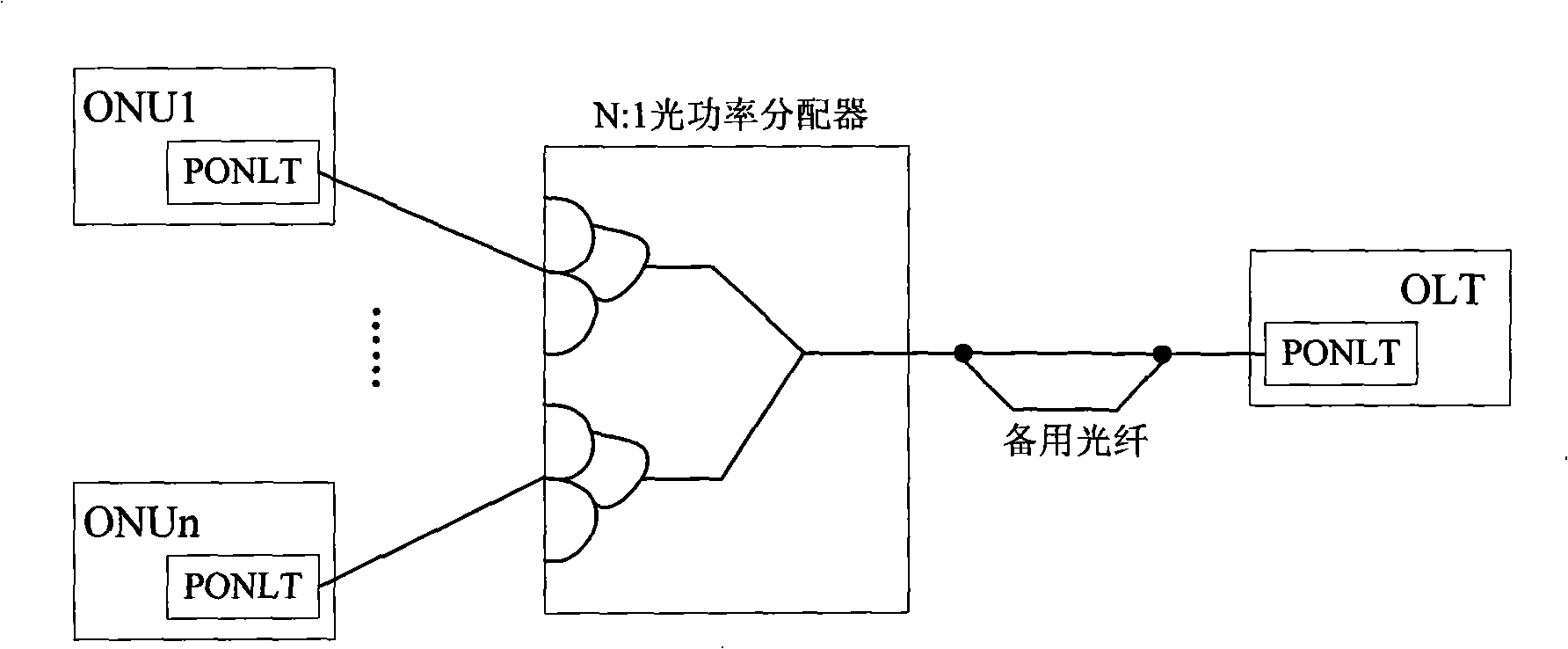
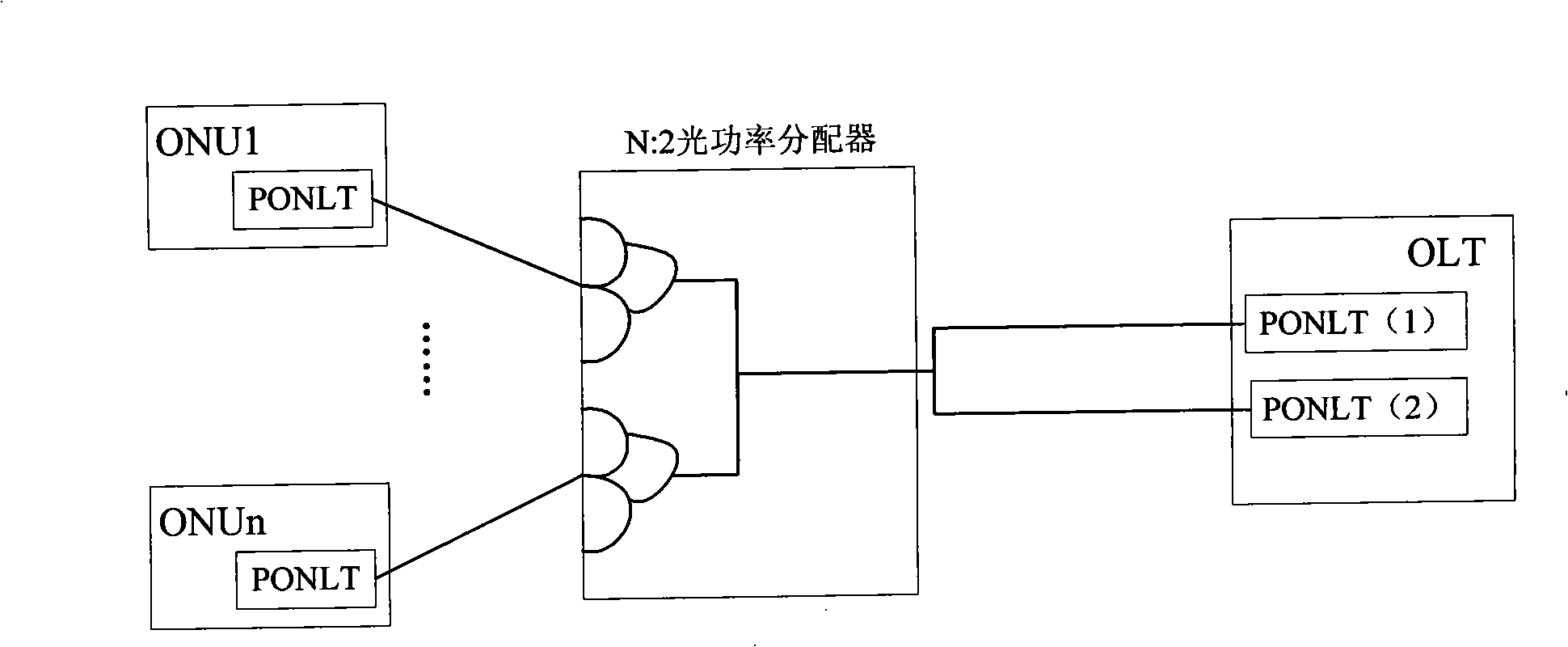
[0056] This embodiment provides a protection switching method based on an Ethernet passive optical network, and the method includes:

[0057] ONU and OLT send APS messages carrying protection switching messages on the protection channel;

[0058] The OLT checks the local switching trigger request and the received APS message, and judges whether to switch according to the local switching trigger request and the protection switching message carried in the APS message. If so, it determines the switching mode according to the local switching trigger request and the protection switching message. The determined switching mode is for backbone fiber switching or branch fiber switching;

[0059] The ONU checks the local switching trigger request and the received APS message, and judges whether to switch according to the local switching trigger request and the protection switching message carried in the APS message. If so, it switches the uplink service to the protection channel and then sw...

Embodiment 2

[0132] See Figure 7 This embodiment provides a protection switching system based on an Ethernet passive optical network, including:

[0133] The optical network unit 301 is used to send an automatic protection switching protocol message to the opposite end on the protection channel, carrying a protection switching message, and to check the local switching trigger request and the received automatic protection switching protocol message, according to the local switching trigger request and The protection switching message carried in the message determines whether to switch, and if so, switches the uplink service to the protection channel, and receives the downlink service from the protection channel;

[0134] The optical line terminal 302 is used to send an automatic protection switching protocol message to the opposite end on the protection channel, carrying a protection switching message; and to check the local switching trigger request and automatic protection switching protocol...

Embodiment 3

[0136] See Figure 8 , This embodiment provides an optical line terminal device, including:

[0137] The message receiving module 401 is configured to receive an automatic protection switching protocol message sent by the optical network unit.

[0138] If more than N (recommended N=3) transmission cycles (T), no automatic protection switching protocol message is received, it is considered that the opposite end optical network unit is invalid, and an alarm is reported.

[0139] The message processing module 402 is configured to verify the automatic protection switching protocol message received by the message receiving module 401, and extract the switching status information from the automatic protection switching protocol message.

[0140] The local request processing module 403 is configured to collect local switching trigger requests. The local switching trigger requests include external commands and trigger events for automatic protection switching.

[0141] The protocol proces...


PUM


Abstract

The present invention discloses a protection switching method based on an Ethernet passive optical network, a system and a device thereof, belonging to the field of communication. The method comprises the following steps: the ONU and OLT send an ASP message with the protection switching information on a protection channel; the OLT checks the local switching triggering request and the ASP message, judges whether the switching is required, and determines the switching mode, according to the triggering request and the protection switching information in the report; the main optical fiber or the branch optical fiber is switched by the OLT according to the determined switching mode; the ONU checks the local switching triggering request and the ASP message, and judges whether the switching is required; if the switching is required, the ONU switches the uplink business onto the protection channel and receives the downlink business from the protection channel. The system comprises an optical network unit and an optical line terminal. The protection switching method enhances the switching stability and practicality by judging the main switching or branch switching on the OLT side.

Description

Technical field [0001] The present invention relates to the field of communication, in particular to a protection switching method, system and equipment based on an Ethernet passive optical network. Background technique [0002] See figure 1 , EPON (Ethernet Passive Optical Network, Ethernet passive optical network) is composed of OLT (Optical Line Terminal), ONU (Optical Network Unit, Optical Network Unit) and ODN (Optical Distribution Network, Optical Distribution Network). Among them, ODN is mainly composed of passive components such as passive optical splitters, passive optical attenuators, optical fibers, and optical connectors. EPON combines the advantages of passive technology with strong anti-interference ability, saving fiber resources and low cost of Ethernet technology, and is widely used in FTTH (Fiber To The Home) configurations. However, to use EPON for the access of large customer dedicated lines, it requires strong protection capabilities. The existing EPON prote...

Claims


Application Information

Patent Timeline
Patent Type & Authority Applications(China)
IPC IPC(8): H04B10/20H04L12/56H04B10/032
Inventor 王艳琼王建军
Owner SUZHOU YUDESHUI ELECTRIC TECH CO LTD
Why Eureka
Try Eureka