
By-path interdiction TCP connection

A bypass, network technology, applied in the direction of data exchange, digital transmission system, electrical components, etc. through path configuration, can solve the problem of TCP connection cannot be blocked

Inactive Publication Date: 2009-01-21
莱克斯科技(北京)有限公司
View PDF0 Cites 10 Cited by
  • Summary
  • Abstract
  • Description
  • Claims
  • Application Information

AI Technical Summary

Problems solved by technology

[0003] The purpose of the present invention is to solve the problem that the TCP connection cannot be blocked under the bypass monitoring mode of the network

Method used


Image

  • By-path interdiction TCP connection

Examples


Embodiment Construction

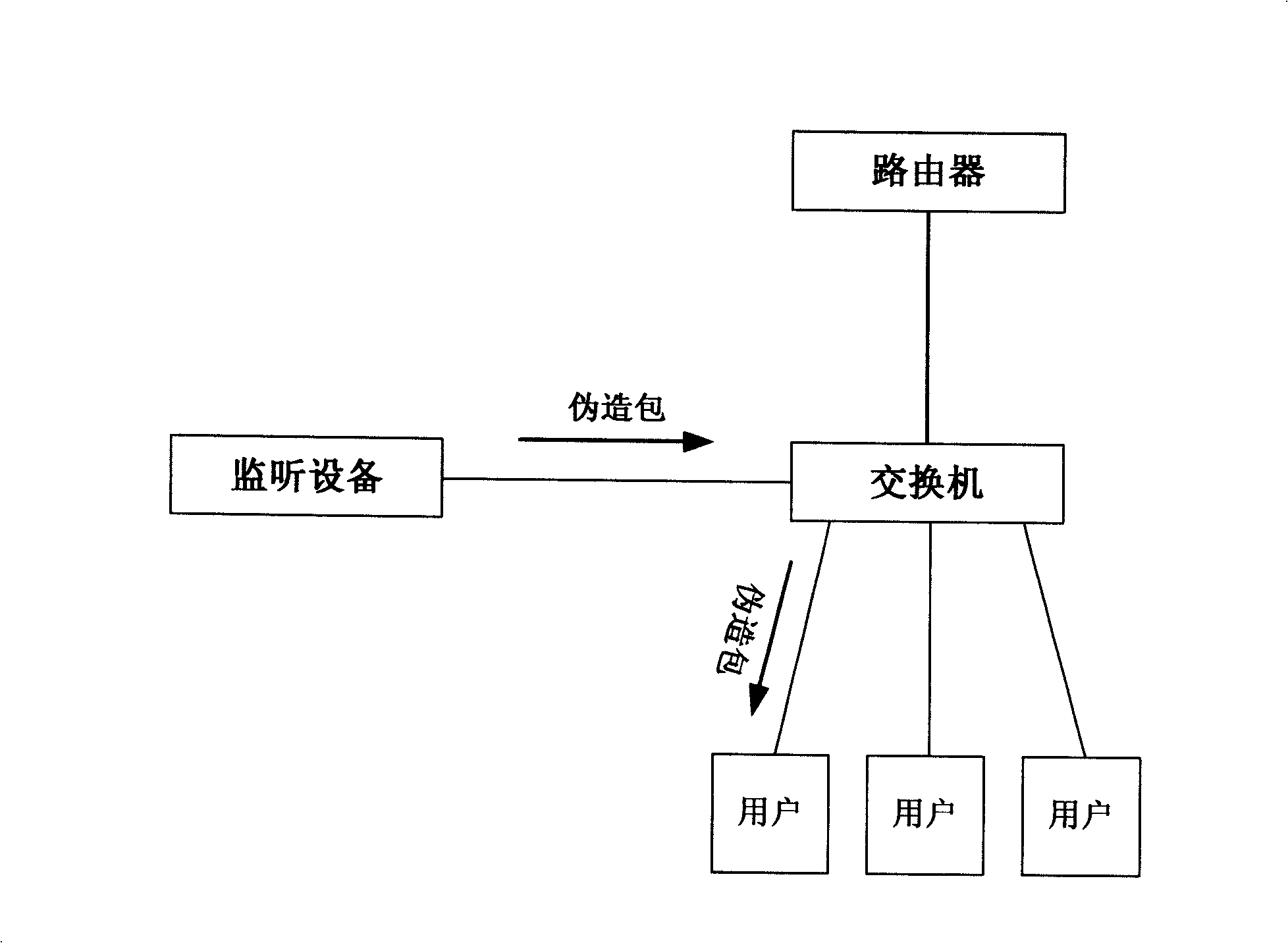
[0033] System implementation figure 1 .

[0034] 1. Connect the monitoring device to the mirror port of the hub or switch for monitoring.

[0035] 2. Identify the TCP connection that needs to be blocked in the monitored data packets.

[0036] 3. Construct a forged RST packet according to the information of the TCP connection that needs to be blocked.

[0037] 4. Send the forged data packet to the link layer with raw socket. Thus blocking specific TCP connections.


PUM


Abstract

The present invention provides a method, which is used for blocking TCP connection of a network in the bypass way. The method can be used in the fields of network security, network management, network access control, and so on. A monitoring device is arranged in a local area network, which is used for monitoring for the network through a hub or the mirror port of an exchanger. When the connection of a TCP needs blocking, an imitative TCP data packet with a RST sign is assembled according to the monitored information of TCP connection; the data packet is then directly transmitted to a link layer. The machine which has the connection to be blocked receives the imitative TCP data packet, and considers that the other end of the connection has transmitted the information of resetting the connection. According to standard protocols, the operating system can automatically disconnect the TCP. Thus the application program with the connection can be disconnected, which achieves the purpose of blocking the illegal network visit.

Description

technical field [0001] The invention is a method for blocking the TCP connection on the network in a bypass mode. It can be used in the fields of network security, network management and network access control. Background technique [0002] At present, in the internal office network of small and medium-sized enterprises, it is necessary to monitor the network usage in the fields of employee network access control, content filtering, content auditing, and network security. Generally, the bypass monitoring method is used to reduce the burden on the gateway or router. But the control function of the bypass has been compromised. The invention can realize the function of blocking a specific TCP connection in the bypass through the way of forging data packets, thereby solving the functional defect of the bypass monitoring mode. Contents of the invention [0003] The purpose of the invention is to solve the problem that the TCP connection cannot be blocked in the bypass monito...

Claims


Application Information

Patent Timeline
IPC IPC(8): H04L12/28H04L12/26H04L12/56H04L12/931
Inventor 尹志超
Owner 莱克斯科技(北京)有限公司
Learn More