Method of measuring position detection error in machine tool

A technology of detection error and positioning error, applied in the field of position detection error, can solve problems such as difficult coverage, and achieve the effect of precise machining

Inactive Publication Date: 2009-01-28
FANUC LTD
View PDF1 Cites 11 Cited by
  • Summary
  • Abstract
  • Description
  • Claims
  • Application Information

AI Technical Summary

Problems solved by technology

However, it is very difficult to provide such coverage in the case of laser ranging in the vicinity of the processing point

Method used


Image

  • Method of measuring position detection error in machine tool
  • Method of measuring position detection error in machine tool
  • Method of measuring position detection error in machine tool

Examples


Embodiment Construction

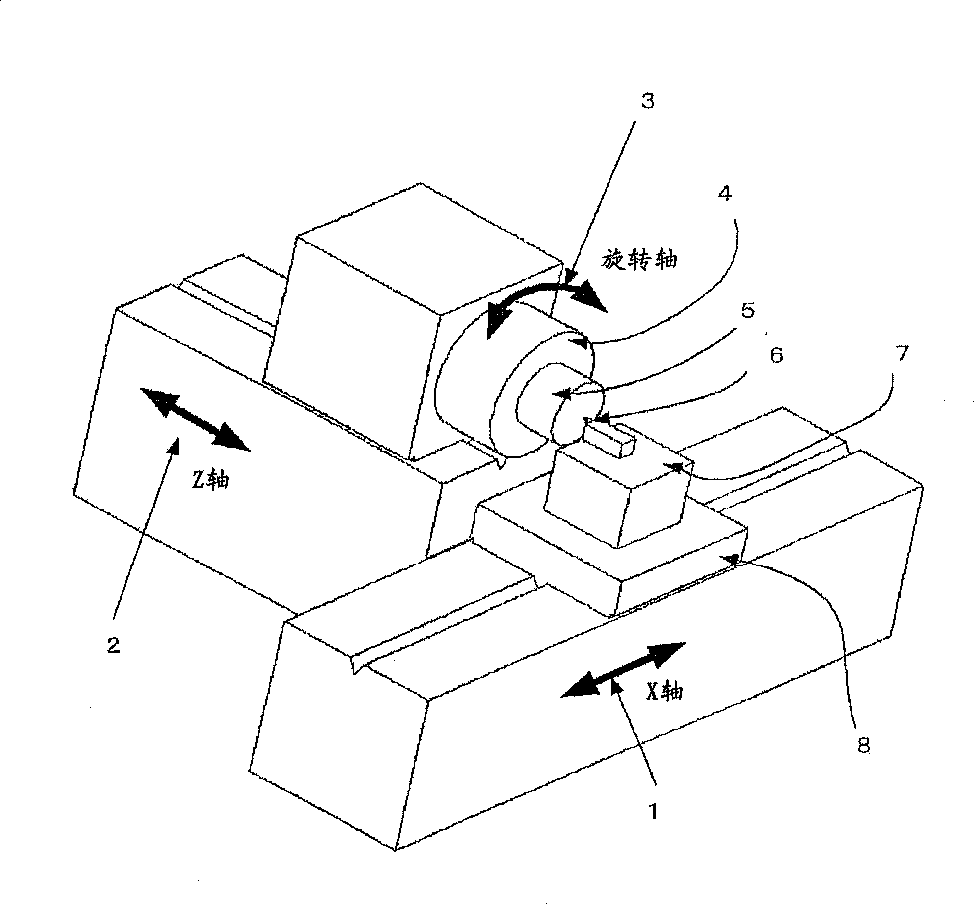
[0023] figure 1 is a perspective view of the main components of a CNC machine tool in which an embodiment of the present invention is implemented, with a linear scale fitted near a machining point on the machine tool.

[0024] A tool 6 and a workpiece 5 are mounted on the CNC machine tool, an X axis 1 and a Z axis 2 are used as two linear axes, and a rotary axis 3 is mounted on the Z axis 2 . A rotary table 4 is mounted on the rotary shaft 3 . The workpiece 5 is detachably fixed in position on the rotary table 4 . The tool holder 7 is detachably assembled on the slider 8 of the X-axis 1 , and the tool 6 is fixedly assembled on the tool holder 7 . In machine tools configured of this type, positioning errors are caused due to pitch, yaw, and roll about each linear axis as described above.

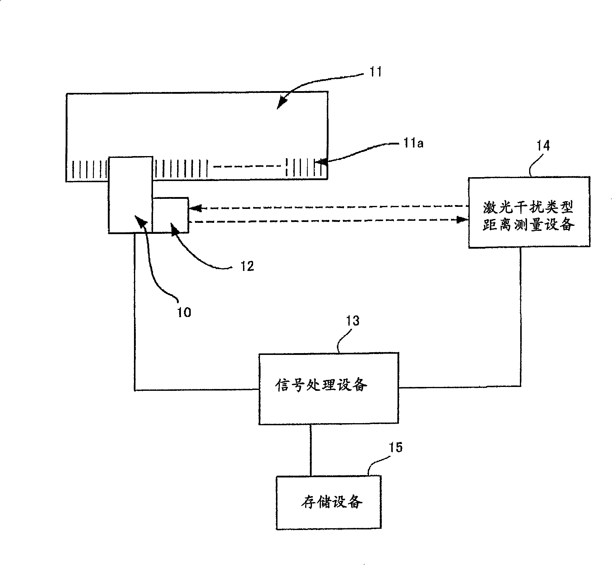
[0025] figure 2 is an example representing an error measuring device designed to improve the absolute accuracy of a positioning error measuring linear scale fitted near a machining poin...


PUM


Abstract

A machine tool position detection error measurement method eliminates the effects of pitch, yaw, and roll of the axes at the point of machining of a CNC machine tool, and improves machining accuracy. The method comprises a step of compensating positioning accuracy of a positioning-error-measuring linear scale using a laser distance-measuring device, a step of mounting the compensated positioning-error-measuring linear scale parallel to a linear axis of the machine tool, and a step of comparing a motion amount obtained from the position detector by moving the linear axis a certain amount and a motion amount read from the positioning-error-measuring linear scale mounted parallel to the linear axis and storing a difference therebetween as error data of the position detector for the machine tool.

Description

technical field [0001] The present invention relates to a method of measuring a position detection error of a position detector provided in a machine tool, and more particularly, to a method of measuring a machining point of a machine tool due to pitch, yaw, and roll A method of positioning errors in proximity, and also relates to compensation of detection data of a position detector using error data obtained by a position detection error measurement method. Background technique [0002] For example, a prior art for improving the position detection accuracy of a linear scale used on an X-Y stage of semiconductor manufacturing equipment includes moving each axis of the X-Y stage by a certain distance at a certain time, using a laser distance measuring device to Measure the actual distance of movement, calculate the difference between the commanded movement distance and the actual movement distance, and use the obtained difference data to improve the position detection accurac...

Claims


Application Information

Patent Timeline
Patent Type & Authority Applications(China)
IPC IPC(8): B23Q17/24G01B21/00G01C3/00
CPCG05B2219/37024G05B19/18G05B2219/37504G05B2219/37325G05B2219/37027
Inventor 河合知彦蛯原建三小田隆之
Owner FANUC LTD
Why Eureka
Try Eureka