Full automatic silt separation apparatus

A fully automatic technology for sediment separation, applied in water conservancy projects, marine engineering, coastline protection, etc., can solve problems such as the inability of hydro-generator units, and achieve the effects of water saving, reliable performance and easy implementation

Inactive Publication Date: 2009-01-28
黄国宏
View PDF4 Cites 12 Cited by
  • Summary
  • Abstract
  • Description
  • Claims
  • Application Information

AI Technical Summary

Problems solved by technology

The wear and tear of water turbines in hydropower production is particularly serious, making it impossible for the water turbine generator set to operate safely, stably, continuously and efficiently

Method used


Image

  • Full automatic silt separation apparatus
  • Full automatic silt separation apparatus
  • Full automatic silt separation apparatus

Examples


Embodiment Construction

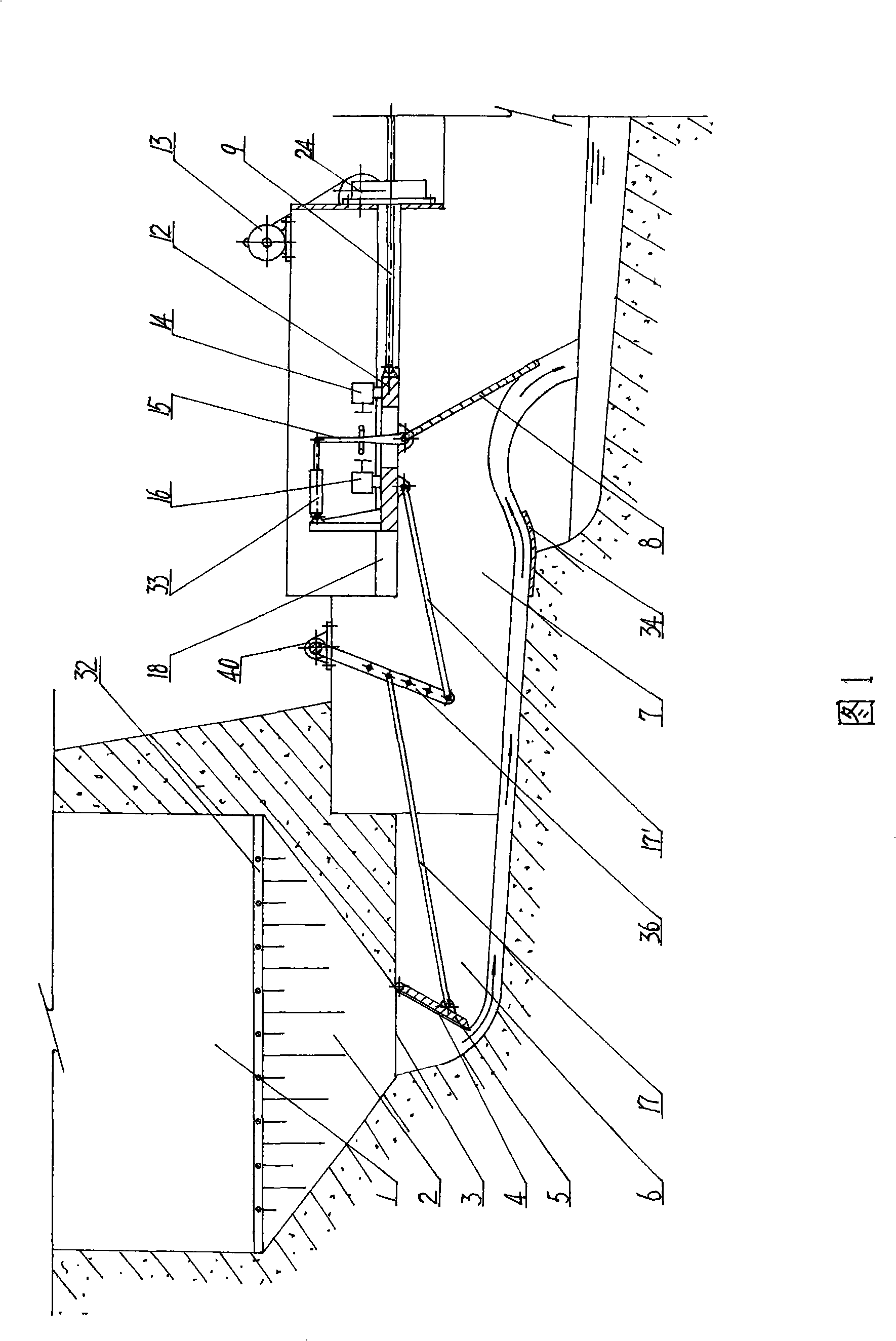
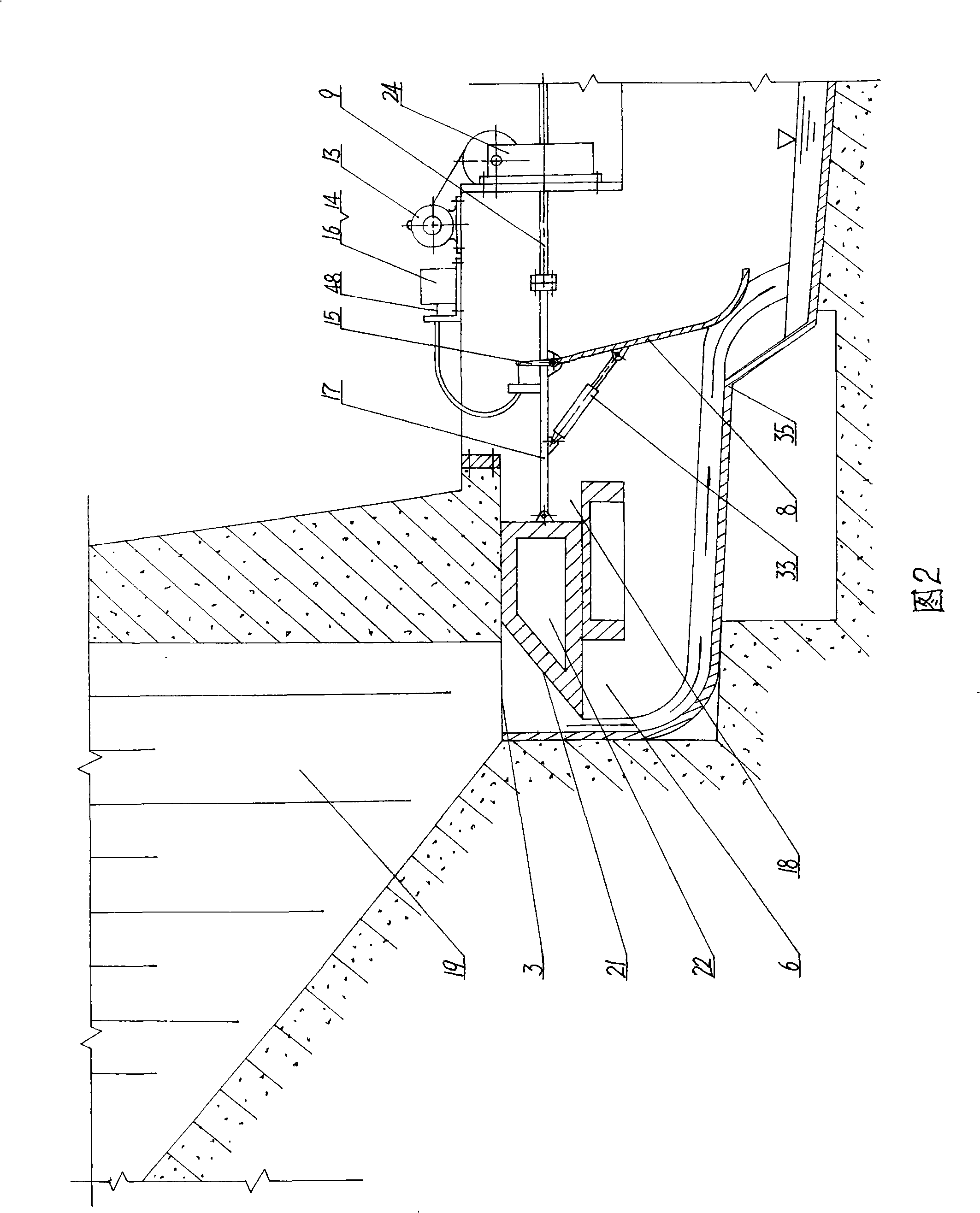
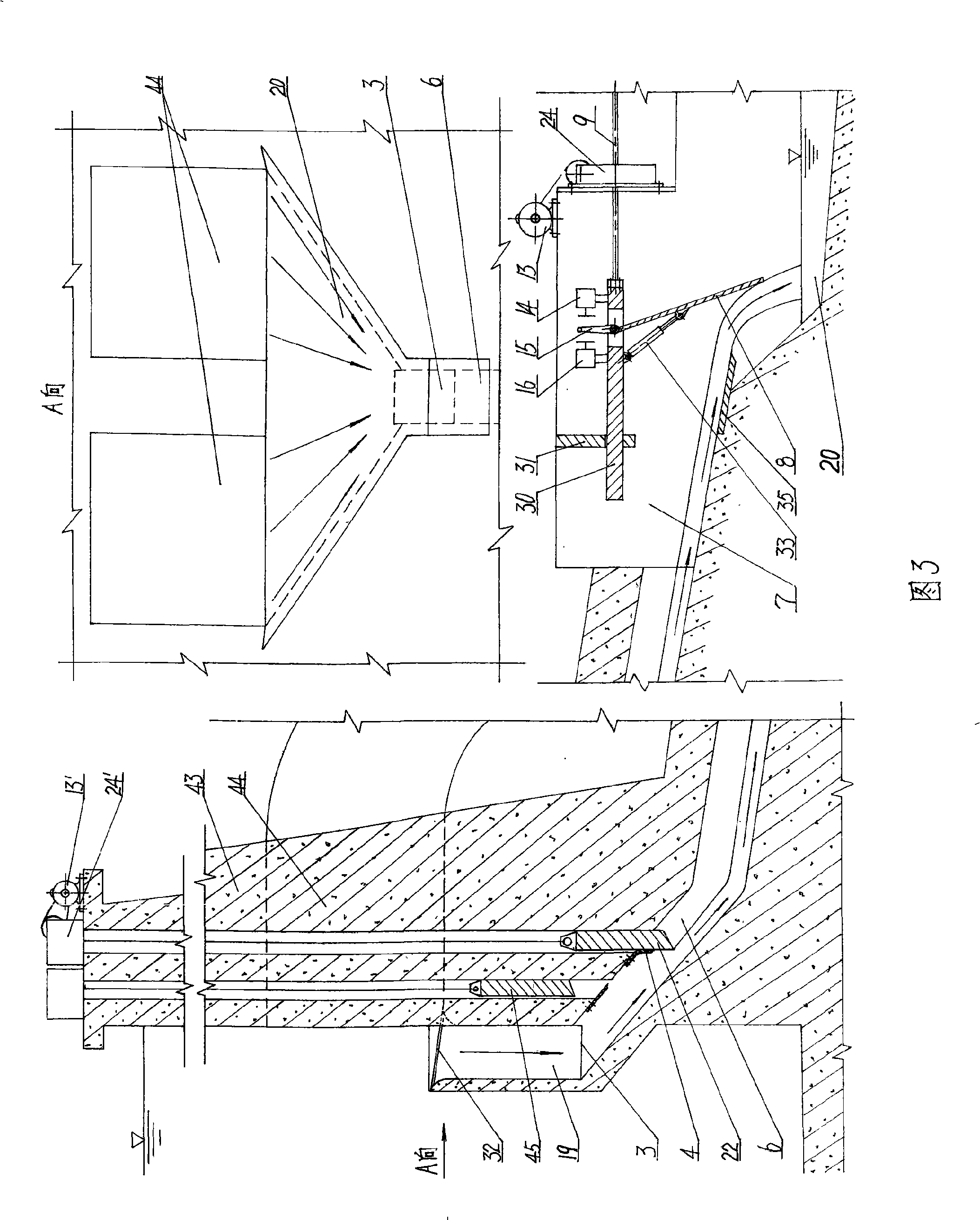
[0032] Figure 1 shows the first embodiment of the present invention.

[0033] As shown in Figure 1: At the bottom of the water diversion channel 1, a trapezoidal groove 2 is extended, and the bottom of the trapezoidal groove 2 is provided with a horizontally arranged rectangular sand outlet 3, and the rectangular sand outlet 3 is connected with a row with a certain slope at the bottom. The outlet end of the sand flow channel 6 and the sand discharge flow channel 6 is connected to the water drop flow channel 7 provided with a ridge 34. A trash rack 32 is installed horizontally on the top surface of the trapezoidal groove 2. A rectangular sand discharging throttle plate 5 is hinged on the edge of the rectangular sand discharging port 3 connected to the top surface of the sand discharging channel 6, and the two sides and hinged ends of the sand discharging throttle plate 5 are provided with seals 4. When the sand discharging throttle plate 5 is hanging down, a driving rod 17 is hinge...


PUM


Abstract

The invention discloses a full-automatic silt separation device which relates to a full-automatic mechanical device which automatically separates silt brought by water current in a water passage or a silt sedimentation tank in time and automatically adjusts the desilting flow rate in time. The device is composed of a desilting throttle disc or a desilting throttle block which is arranged in the water passage, under a desilting port at the bottom of the silt sedimentation tank, or in a desilting passage, an automatic regulating device which is linked with the desilting throttle disc or the desilting throttle block by a transmission component or an electric circuit and arranged in the desilting passage connected with the desilting port, a power plant, an electric component and the electric circuit, etc. The device not only can automatically separate the silt brought by water current by means of own structure in time, but also can automatically adjust the desilting flow rate in time according to the content of the silt, thereby being capable of completely separating the slit brought by water current under the condition of controlling the desilting flow rate to be in minimization.

Description

Technical field [0001] The invention relates to a fully automatic mechanical device that automatically separates the sediment brought by the water flow in a water flow channel or a sediment sedimentation tank in time, and automatically adjusts the sediment discharge flow in time. Background technique [0002] At present, the separation of sediment in water conservancy projects mainly relies on the discharge holes or outlets at the bottom of the water flow channels, dams or sediment sedimentation tanks, which are connected to the outlets of the sand outlets or outlets, and are horizontally separated. Sand discharge corridors or pipelines arranged in the direction, and a sand gate or gate valve installed on a certain cross section of the sand discharge corridor or pipeline to discharge sand. Its shortcomings are: because there is a pressurized undercurrent in front of the sand gate or the sand gate valve, the ability of the water to carry the sediment is very weak, and the sediment...

Claims


Application Information

Patent Timeline
Patent Type & Authority Applications(China)
IPC IPC(8): E02B8/02
Inventor 黄国宏
Owner 黄国宏
Why Eureka
Try Eureka