Supercharge Your Innovation With Domain-Expert AI Agents!

Magnetic floating and magnetic moving horizontal fan shaft windmill electric generating apparatus

A windmill power generation and magnetic motion technology is applied in the field of permanent magnet suspension windmill, magnetomotive transmission of windmill torque, and integration of windmill and power generation device, which can solve the problems of reducing economic life, difficult installation, and excessive "tip speed ratio", etc. Achieve the effect of reducing frictional resistance, improving power generation efficiency, and increasing working wind speed

Inactive Publication Date: 2011-08-17
李岭群
View PDF0 Cites 0 Cited by
  • Summary
  • Abstract
  • Description
  • Claims
  • Application Information

AI Technical Summary

Problems solved by technology

The shortcoming of this technology is: 1, a wind turbine corresponds to a generator, the wind speed is low and can not generate electricity, and the wind speed must adopt " turn the head ", " raise the head ", " turn the nacelle to face the wind angle ", " change pitch. In essence, it is a waste of wind energy; 2. The power generation capacity is low, the world's leading level is 3MW, and the research and development is 7MW
The diameter of the wind rotor of the 3MW wind turbine has reached 130 meters, and the tower height is nearly 80 meters, which is difficult to install and maintain; 3. The wind blades have poor adaptability to surface turbulent wind, and only elevated wind turbines can work effectively; 4. The rotational speed of the shaft is low, and the "tip speed ratio" is too large (that is, the tip line speed of the wind rotor blade is too large), which not only produces a lot of noise, but also reduces the economic life; 5. High cost: 80,000 RMB / kW

Method used


Image

  • Magnetic floating and magnetic moving horizontal fan shaft windmill electric generating apparatus
  • Magnetic floating and magnetic moving horizontal fan shaft windmill electric generating apparatus
  • Magnetic floating and magnetic moving horizontal fan shaft windmill electric generating apparatus

Examples


Embodiment Construction

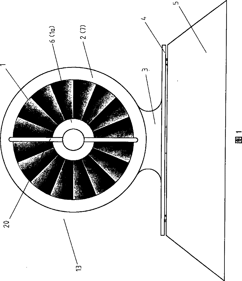
[0037] The present invention consists of seven parts: rotating fan body, outer structure ring, steering base, rotating fan body permanent magnetic levitation, crawler magnetic motor and generator, steering base permanent magnetic levitation, steering magnetic motor, and fairing, wherein:

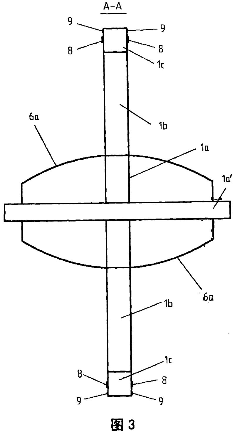
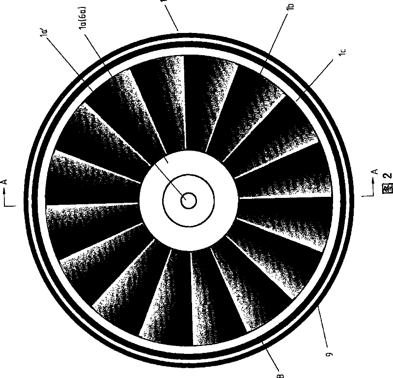
[0038] Rotary fan body part: It consists of three parts: the rotating fan hub, the rotating fan ring and the rotating fan. The fan hub is set in the center of the fan body and is made of metal such as but not limited to aluminum alloy. It is a structural part connecting the fan. The fan shaft is arranged in the center of the fan hub and is made of metal (such as but not limited to carbon steel). . The rotating fan ring is arranged on the outer ring of the rotating fan body, and is made of metal (such as but not limited to aluminum alloy), and its inner edge is connected with the rotating fan. On both sides of the rotating fan ring, there are respectively ring-shaped linear stator shoes and ...


PUM


Abstract

The invention discloses a magnetically suspended and moved windmill generating device with a horizontal fan axis; a fan rotating ring of a fan rotating body is held in an external structure ring; an external fairing and an internally-rotating fairing not only enlarge the air-inlet area, but also shrink the area of a fan rotating mouth segment, thereby increasing the work wind speed of a rotating fan; the central axes of two internal lateral faces of the external fairing are respectively provided with a fan rotating beam; a fan axis is horizontally arranged between the two fan rotating beams; a caterpillar-type magnetic motion machine on the external structure ring corresponds to a straight-line stator shoe on the fan-rotating body, thereby realizing a non-contact transmission torque, reducing frictional resistance and increasing the generation efficiency of generators. Multiple generators adopted correspond to the fan rotating body, and the number of the generators is determined by the local highest wind speed; the work quantity of accessing (quitting) generators is controlled by a microcomputer and transformed into an alternating current by an inverter and merged into a power system. When the wind direction changes, the microcomputer measures the changed angle according to an anemoscope and controls the magnetic motion machine to rotate for a corresponding angle so that a horn mouth faces the wind from time to time.

Description

technical field [0001] The invention belongs to the technical field of wind power generation. It specifically involves the technology of permanent magnetic levitation windmill, magnetic motor transmission of windmill torque, and integrated integration of windmill and power generation device. Background technique [0002] At present, the widely used wind turbines are "three-leaf water-horizontal axis wind turbines". It consists of slender rods: blades and towers and a horizontal shaft to form a wind turbine, which converts wind energy into kinetic energy, and is connected to a generator at the end of the horizontal shaft to generate electricity. The shortcoming of this technology is: 1, a wind turbine corresponds to a generator, the wind speed is low and can not generate electricity, and the wind speed must adopt " turn the head ", " raise the head ", " turn the nacelle to face the wind angle ", " change pitch. The effect of wind power on windmill blades is actually wasted ...

Claims


Application Information

Patent Timeline
Patent Type & Authority Patents(China)
IPC IPC(8): F03D9/00F03D1/06F03D11/00F03D7/02F03D1/04H02N15/00F16C32/04F03D9/25F03D13/20
CPCY02E10/723Y02E10/722Y02E10/721Y02E10/72
Inventor 李岭群
Owner 李岭群
Features
  • R&D
  • Intellectual Property
  • Life Sciences
  • Materials
  • Tech Scout
  • Unparalleled Data Quality
  • Higher Quality Content
  • 60% Fewer Hallucinations
Learn More