Coil tube type steam generation apparatus

A steam generating device and steam technology applied in the field of pressure vessels to achieve good energy saving effect, high steam generation rate and wide heating area

Inactive Publication Date: 2009-01-28
常州能源设备总厂有限公司
View PDF0 Cites 9 Cited by
  • Summary
  • Abstract
  • Description
  • Claims
  • Application Information

AI Technical Summary

Problems solved by technology

[0002] The evaporator currently used is mainly in the form of an evaporating pot. The evaporating pot mainly uses fire or a steam jacket to directly heat and evaporate th

Method used


Image

  • Coil tube type steam generation apparatus

Examples


Example Embodiment

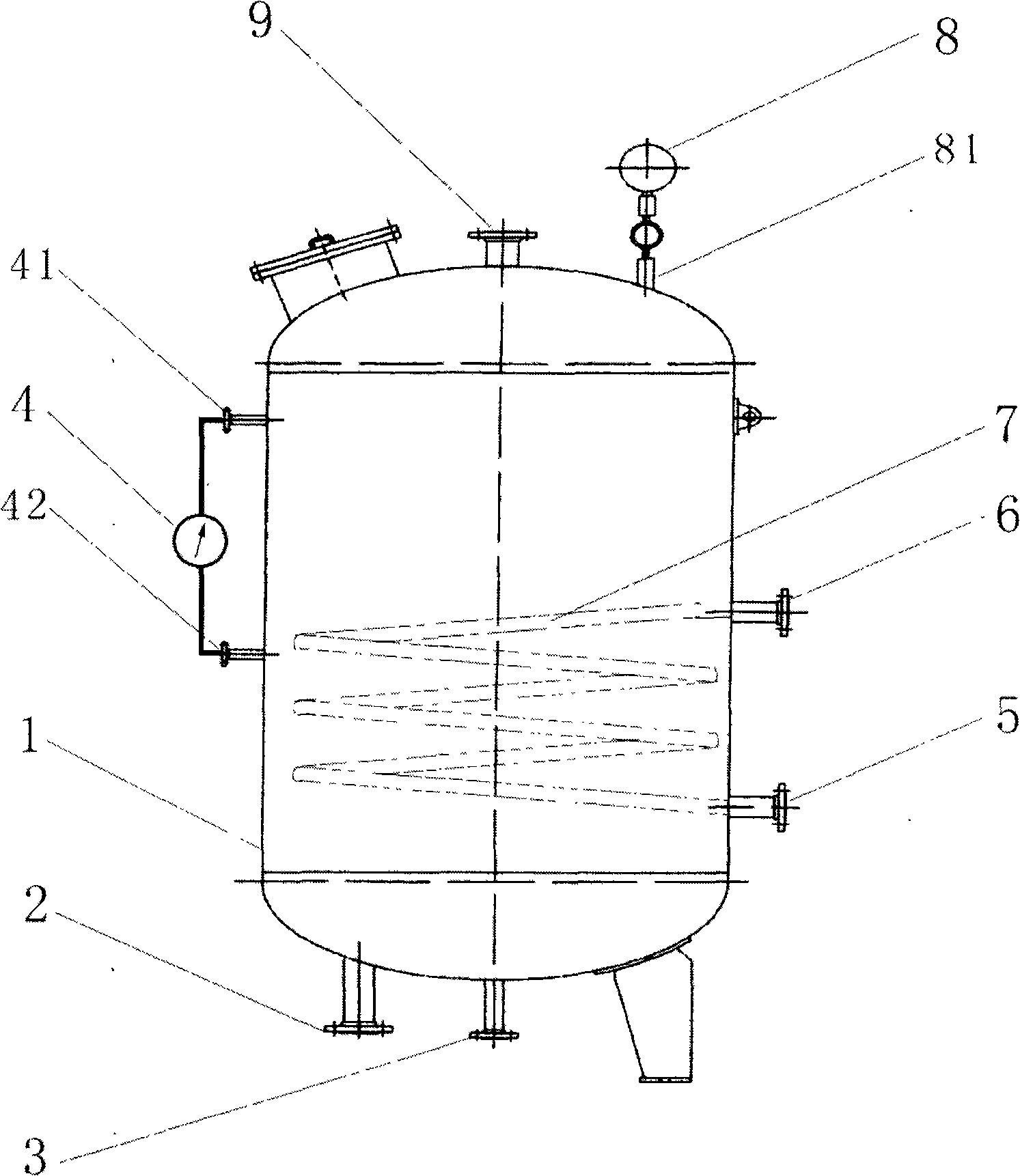
[0008] The utility model consists of a pressure vessel (1), a soft water inlet (2), a sewage outlet (3), a liquid level gauge (4), a heat conduction oil inlet (5), a heat conduction oil outlet (6), and a heat conduction oil coil (7). ), pressure gauge (8), steam outlet (9) and other parts.

[0009] The utility model adopts a pressure vessel (1) constructed of carbon steel material, which can withstand a maximum pressure of 3.0MPa, and is provided with a soft water inlet (2), a sewage outlet (3) and an upper interface on the level gauge on the periphery of the pressure vessel (1) (41), the lower interface of the level gauge (42), the heat conduction oil inlet (5), the heat conduction oil outlet (6), the pressure gauge interface (81), the steam outlet (9); the soft water inlet (2), the sewage outlet (3) The heat-conducting oil inlet (5), heat-conducting oil outlet (6), steam outlet (9) and the outside world are all connected by flanges. Install a level gauge (4) on the upper and low...


PUM


Abstract

The invention discloses a steam generation device. High-temperature heat-conducting oil is conveyed in a pipeline so that heat exchange is fully conducted between heat in the pipeline and inputted soft water, therefore, water is heated to a heat transfer surface under natural convection to realize continuous boiling and saturated steam can be generated under a certain pressure and then outputted from a steam outlet.

Description

technical field [0001] The invention relates to a pressure vessel, in particular to a coil type steam generating device. The invention is a device that uses high-temperature heat-conducting oil to exchange heat with water to generate steam. Background technique [0002] The evaporator currently used is mainly in the form of an evaporating pot. The evaporating pot mainly uses fire or a steam jacket to directly heat and evaporate the liquid. At present, there is no device that generates steam by using high-temperature heat transfer oil and water to exchange heat. The present invention filled this gap. Contents of the invention [0003] The invention utilizes the heat generated by the high-temperature heat-conducting oil to fully exchange heat with the soft water input into the steam generating device, heats the input soft water to the maximum extent to reach the boiling point of the soft water in the pressure vessel, and forms a large amount of steam from the steam generati...

Claims


Application Information

Patent Timeline
IPC IPC(8): F22B1/16F22B37/22F22B37/78
Inventor 李光金海鸥丁宏贡建岗
Owner 常州能源设备总厂有限公司
Why Eureka
Try Eureka