Display apparatus

A technology of display equipment and brightness distribution, applied in static indicators, TVs, color TVs, etc., can solve problems such as difficult contrast, uneven brightness, and increased manufacturing costs

Inactive Publication Date: 2009-01-28
SONY CORP
View PDF1 Cites 2 Cited by
  • Summary
  • Abstract
  • Description
  • Claims
  • Application Information

AI Technical Summary

Problems solved by technology

[0008] Therefore, when changing the angle-dependent luminance distribution of display light, it is difficult for the above-mentioned prior art to achieve, for example, improvement of contrast ratio and reduction of luminance unevenness without increasing manufacturing cost.

Method used


Image

  • Display apparatus
  • Display apparatus
  • Display apparatus

Examples


Embodiment Construction

[0019] Now, preferred embodiments of the present invention will be described in detail with reference to the accompanying drawings.

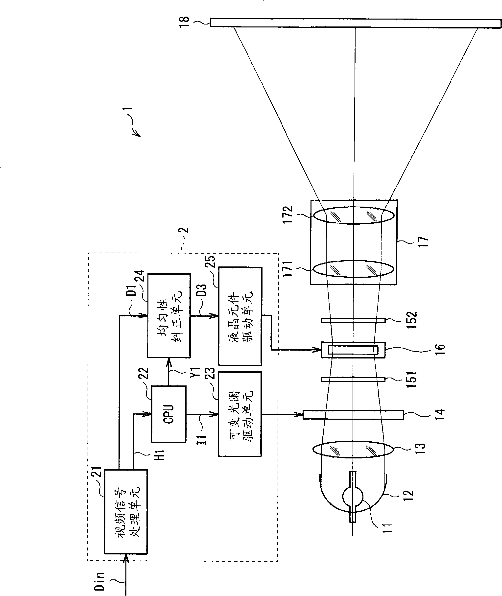
[0020] figure 1 The entire configuration of the display device (liquid crystal projector 1 ) according to the embodiment is shown. The liquid crystal projector 1 is used for displaying images according to an input video signal Din provided outside, and includes: a light source 11, a mirror 12, an illumination optical system 13, an iris diaphragm 14, a polarizer 151, a liquid crystal element 16, an analyzer 152, Projection lens unit 17, screen 18 and controller 2 which controls iris 14 and liquid crystal element 16 according to input video signal Din.

[0021] The light source unit 11 emits white light including red light (R), blue light (B) and green light (G) necessary for color image display, and is configured by, for example, a halogen lamp, a metal halide lamp, or a xenon lamp.

[0022] The reflection mirror 12 reflects light emitted from ...


PUM


Abstract

The present invention provides a display apparatus, which includes: a light source; spatial light modulation device for modulating light emitted by the light source based on a video signal; intensity distribution adjusting means for changing an angle-dependent intensity distribution of an incident light in response to luminance factor in the video signal, the intensity distribution adjusting means being arranged ahead of or behind the spatial light modulation device; and correction means for correcting the video signal in accordance with an intensity distribution adjusted by the intensity distribution adjusting means, and supplying a corrected video signal to the spatial light modulation device, in which the correction means has a plurality of correction tables each corresponding to a predetermined intensity distribution, generates a mixed correction value by mixing correction values in the plurality of correction tables at a mixing ratio determined by an individual intensity distribution, and corrects the video signal by using the mixed correction value.

Description

technical field [0001] The present invention relates to a display device applicable to liquid crystal projectors and the like. Background technique [0002] Projection display devices such as liquid crystal projectors have been widely used, which are configured to display images by subjecting light entering a spatial light modulation device to spatial modulation, and emitting the modulated light, and then displaying images according to electrical signals supplied to the spatial light modulation device. Gathers and projects emitted light. A projection display device generally has a lamp and a condenser lens as light sources, and an illumination optical system for collecting and causing light from the two light sources to enter a spatial light modulation device. Light from the spatial light modulation device is projected onto a screen or the like through a projection lens. [0003] Examples of the above-mentioned projection display device include a projection display device ...

Claims


Application Information

Patent Timeline
Patent Type & Authority Applications(China)
IPC IPC(8): G09G3/36G02F1/13G03B21/00H04N5/74
CPCH04N9/3197H04N9/3182G09G2360/16G09G3/3406G09G2320/0233H04N9/3155G09G3/3611G09G2320/0285G09G3/002G09G2320/0646G09G2320/0633
Inventor 宫内润平井康次
Owner SONY CORP
Why Eureka
Try Eureka