Bone anchoring device

An anchoring device and bone technology, applied in the direction of fixator, internal fixator, internal bone synthesis, etc., can solve problems such as large size, and achieve the effect of reducing manufacturing cost and facilitating operation and processing

Active Publication Date: 2009-02-04
BIEDERMANN TECH GMBH & CO KG
View PDF7 Cites 18 Cited by
  • Summary
  • Abstract
  • Description
  • Claims
  • Application Information

AI Technical Summary

Problems solved by technology

In addition, since the locking ring and locking nut extend substantially outwardly f...

Method used


Image

  • Bone anchoring device
  • Bone anchoring device
  • Bone anchoring device

Examples


Embodiment Construction

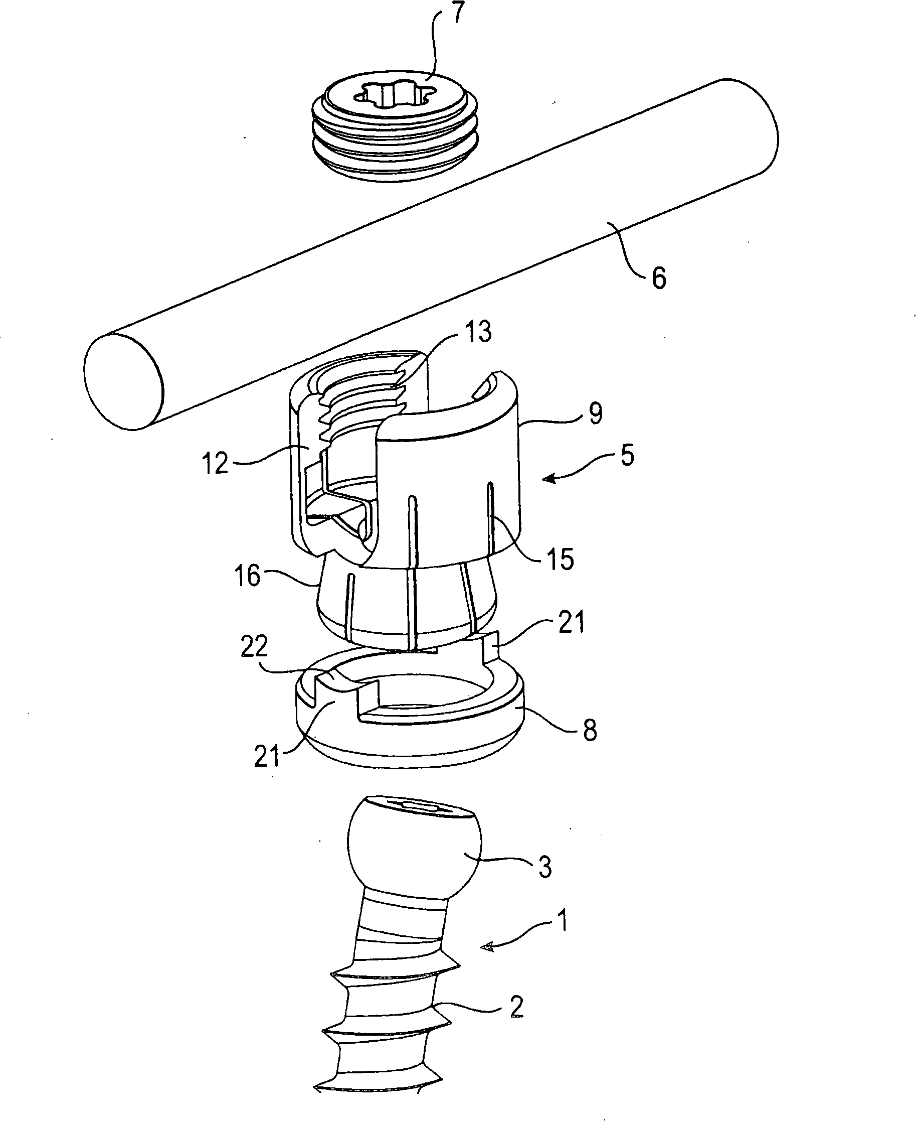
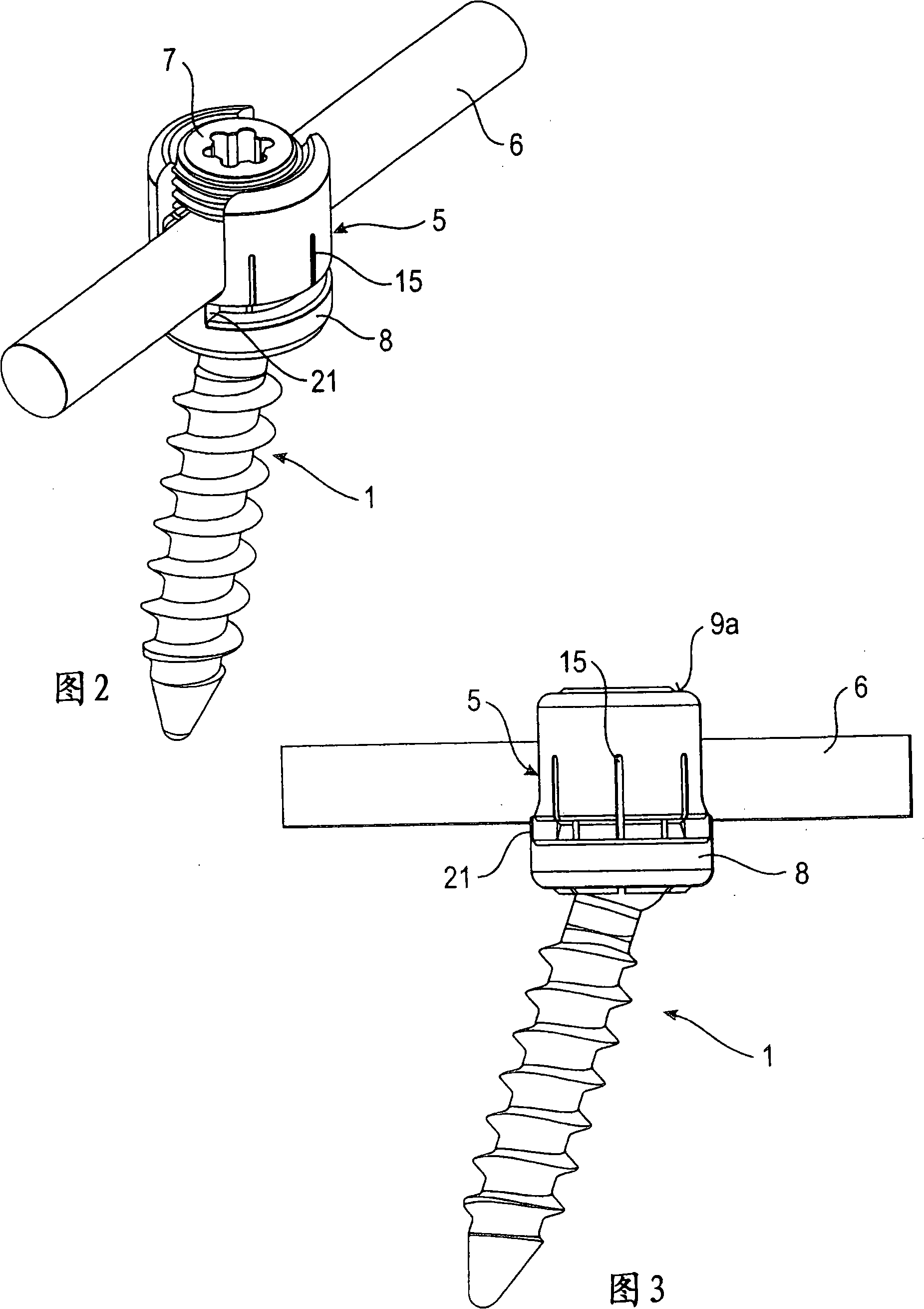
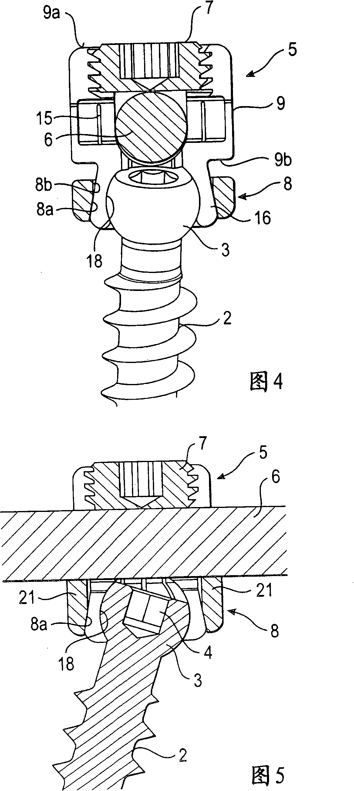
[0036] Such as figure 1 As shown in FIG. 5 , the bone anchoring device according to the first embodiment comprises a bone anchor 1 in the form of a bone screw with a threaded shaft 2 and a spherical head 3 . The head 3 has a recess 4 for engagement with a screw-in tool. The bone anchoring device also comprises a receiving part 5 for receiving a rod 6 to connect the rod 6 to the bone anchor 1 . Furthermore, a closure 7 in the form of an internal screw or set screw is provided for fastening the rod 6 in the receiving part 5 . In addition, the bone anchoring device comprises a locking ring 8 for locking the head in the receiving part 5 .

[0037] In particular, as can be seen in FIGS. 6 to 10 , the receiving part 5 comprises a first portion 9 which is substantially cylindrical and has a first end 9a and an opposite second end 9b. The first part 9 has a coaxial first hole 10 provided at the second end 9b. The diameter of the first hole 10 is smaller than the diameter of the he...


PUM


Abstract

A bone anchoring device is provided, comprising a bone anchoring element having a shaft for anchoring in the bone and a head; a receiving part for coupling a rod to the bone anchoring element, wherein the receiving part comprises a first portion with a first end and a second end and a U-shaped recess for receiving the rod, the recess extending from the first end in the direction of the second end thereby forming two free legs and a second portion at the side of the second end opposite to the first end for accommodating the head, the second portion having a free end and being flexible so as to allow introduction and clamping of the head; a locking ring embracing the second portion; wherein the head is locked by means of exerting pressure with the rod onto the locking ring resulting in compression of the second portion of the receiving part and wherein the locking ring is mounted to the receiving part from the free end of the second portion.

Description

technical field [0001] The invention relates to a bone anchoring device comprising a bone anchor and a receiving part for connection to a rod. The head of the bone anchor is locked in the receiving part by pressing a part of the receiving part laterally around the head of the bone anchor by means of the locking ring pressed down by the rod. Said part of the clamping head of the receiving part is designed to allow the locking ring to be mounted from the free end of said part. The bone anchoring device may be implemented eg in the form of a polyaxial bone screw allowing pivotal movement of the head, or a uniaxial bone screw allowing rotational movement of the head about a single axis in the unlocked state, respectively. Background technique [0002] Various designs of polyaxial bone screws are known, wherein each design has specific features and uses different locking principles. [0003] DE 43 05 576 C1 describes a polyaxial bone screw with a screw part, a receiving part an...

Claims


Application Information

Patent Timeline
IPC IPC(8): A61B17/70
CPCA61B17/7032A61B17/7037A61B17/58A61B17/60A61B17/7034
Inventor L·比德尔曼W·马蒂斯B·丹内克尔
Owner BIEDERMANN TECH GMBH & CO KG
Why Eureka
Try Eureka