The
laser machine tool for
machining of workpieces e.g. sheet metals by penetrating a
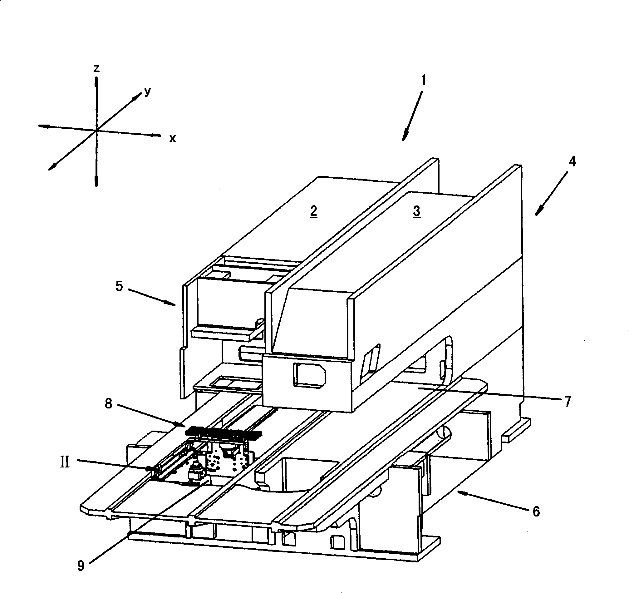
laser beam (15), comprises a workpiece support (8) for holding the workpiece, a
laser machining head and a beam
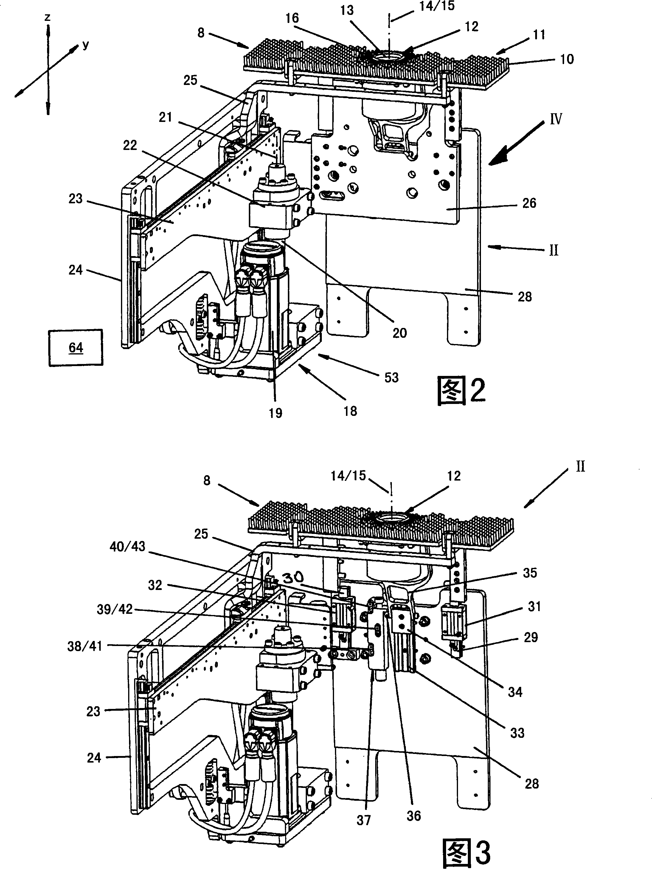
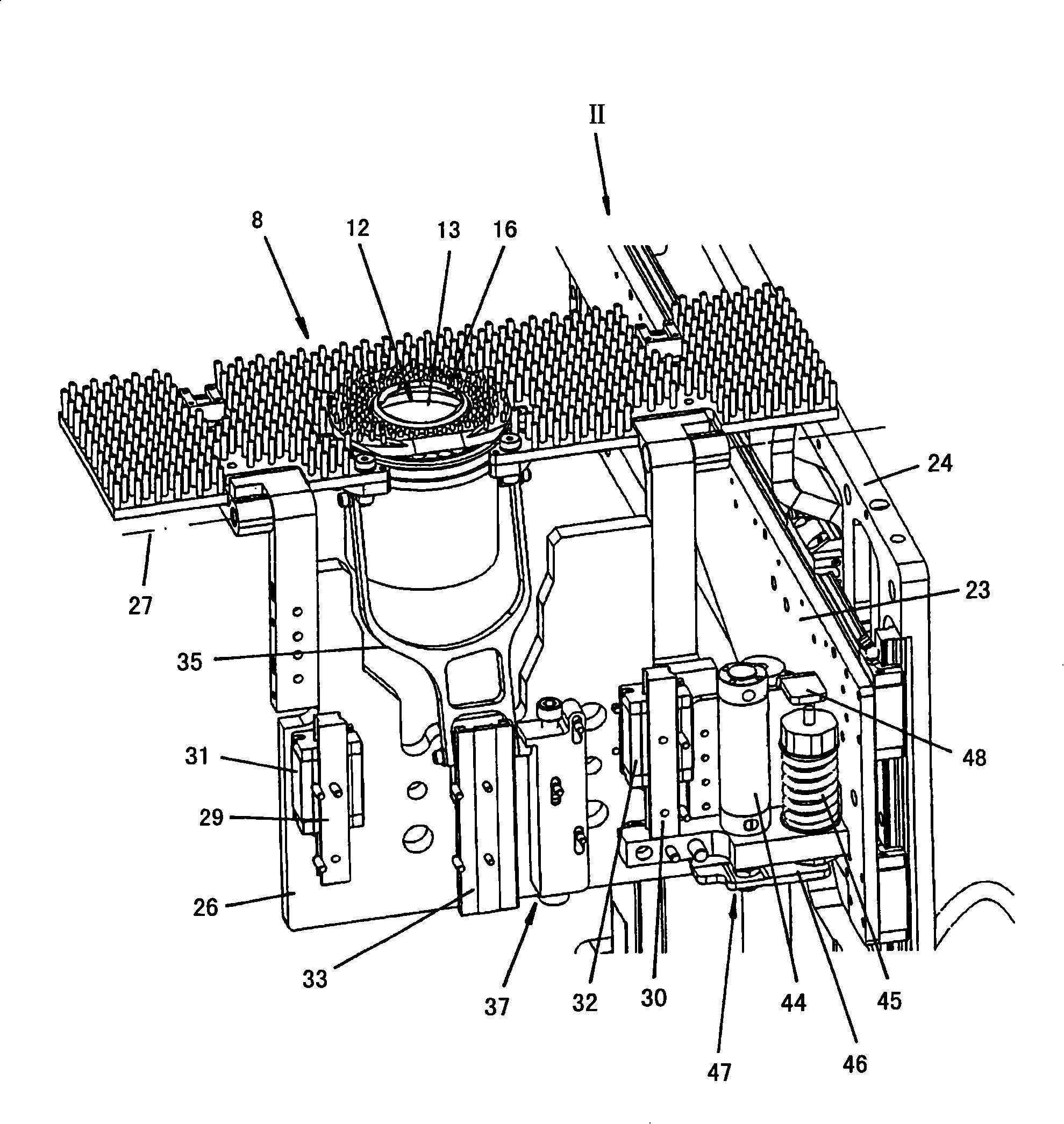
receiver (12)provided with a reception opening (13) for the laser beam, and a positioning device. The laser
machining head is arranged on one side of the workpiece, and the workpiece support and beam
receiver are arranged on the opposite side of the workpiece. The laser beam from the laser machining head after penetrating the workpiece is absorbed into the reception opening of the beam
receiver. The laser
machine tool for machining of workpieces e.g. sheet metals by penetrating a laser beam (15), comprises a workpiece support (8) for holding the workpiece, a laser machining head and a beam receiver (12)provided with a reception opening (13) for the laser beam, and a positioning device. The laser machining head is arranged on one side of the workpiece, and the workpiece support and the beam receiver are arranged on the opposite side of the workpiece. The laser beam from the laser machining head after penetrating the workpiece is absorbed into the reception opening of the beam receiver. The distance between the workpiece and the beam receiver existing along a beam axis (14) of the laser beam absorbing into the beam receiver is variable by the positioning device, so that the workpiece support and the beam receiver are adjustable relative to each other by an
actuator of the positioning device with a positioning movement along the beam axis of the laser beam. The sum of the positioning movement is variably definable. The distance between the workpiece and the beam receiver is adjustable to different spacer values arranged in each case of a machining phase of the workpiece machining, and is adjustable to a larger spacer value for the positioning movement than for the machining movement. The workpiece and the beam receiver are movable relative to each other parallel to a support level formed at the workpiece support when switching-off the laser beam with the positioning movement. The workpiece is machined by the laser beam during a common rest condition of the workpiece and the beam receiver. The distance between the workpiece and the beam receiver is adjustable to the spacer value of zero assigned on a common movement condition of workpiece and the beam receiver, and is adjustable to the spacer value assigned to the material of the workpiece and assigned to the thickness of the workpiece. A drive control is provided for the
actuator. The
actuator is controlled by the drive control, so that distance between the workpiece and the beam receiver is kept at a constant spacer value by corresponding mutual adjustment of the workpiece support and the beam receiver along the beam axis during the duration of the machining phase. The drive control for adjusting the distance between the workpiece and the beam receiver is partially formed by other drive control of further actuator for adjusting the mutual distance between the laser machining head and the workpiece. The distance between the workpiece and the beam receiver is adjustable to an empirically determined spacer value, which is fixed in a memory of a numeric drive control of the actuator. A device for determining the spacer values to be adjusted for the distance between the workpiece and the beam receiver is partially formed by a device for determining the distance between the laser machining head and the workpiece existing along the beam axis. The actuator for mutually adjusting the workpiece support and the beam receiver comprises an actuating motor, by which the workpiece support is adjustable relative to the beam receiver along the beam axis when the beam receiver is stationary or by which the beam receiver is adjustable relative to the workpiece support along the beam axis when the workpiece support is stationary. The actuator for mutually adjusting the workpiece support and the beam receiver is formed by a separating drive and a control drive, by which the workpiece support and / or the beam receiver is movable along the beam axis for separating the products of the workpiece machining. The workpiece support is adjustable relative to the beam receiver during the blocking of the beam receiver in the direction of the movement of the workpiece support or the beam receiver is adjustable relative to the workpiece support during the blocking of the workpiece support in the direction of the movement of the beam receiver. An effective
impact for the beam receiver or the workpiece support is provided in the direction of the adjustment movement for blocking the beam receiver or the workpiece support during the adjustment of the workpiece support and the beam receiver. The
impact is adjustable in different positions. Independent claims are included for: (1) a method for machining of workpieces e.g. sheet metals by penetrating a laser beam; (2) a machining program for operating a laser
machine tool; (3) a method for creating a machining program; and (4) a
computer program product.

