
Laser processing machine for machining workpieces and machine method for machining workpieces using a laser beam

A technology of laser processing and mechanical methods, applied in the fields of processing workpieces, sheet metal, and computer program products

Inactive Publication Date: 2009-02-04
TRUMPF WERKZEUGMASCHINEN GMBH & CO KG
View PDF1 Cites 4 Cited by
  • Summary
  • Abstract
  • Description
  • Claims
  • Application Information

AI Technical Summary

Problems solved by technology

Existing laser processing equipment has only a single position for the laser beam receiver for cutting operations using the aforementioned upper position

Method used


Image

  • Laser processing machine for machining workpieces and machine method for machining workpieces using a laser beam
  • Laser processing machine for machining workpieces and machine method for machining workpieces using a laser beam
  • Laser processing machine for machining workpieces and machine method for machining workpieces using a laser beam

Examples


Embodiment Construction

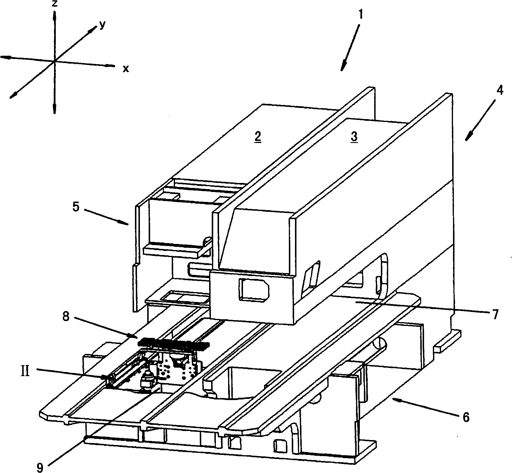
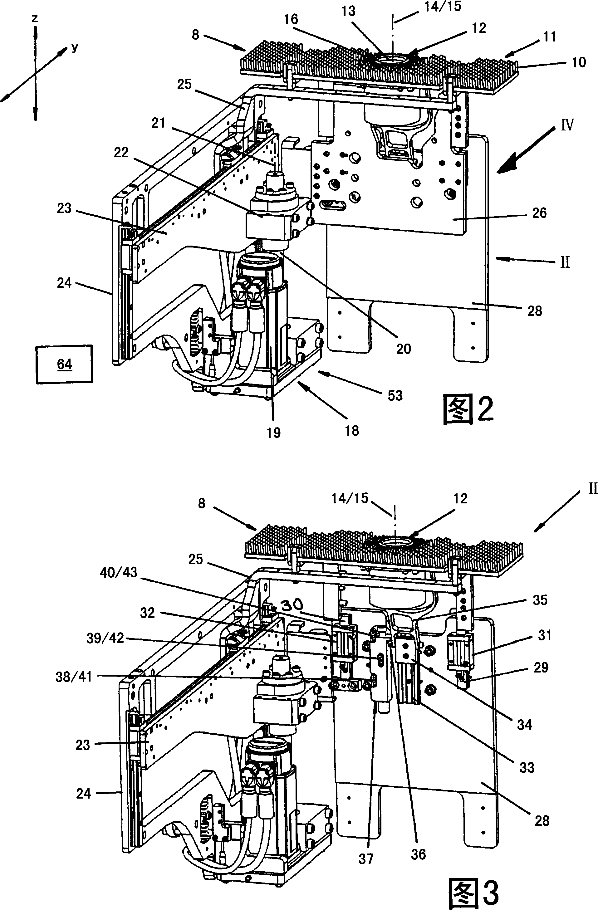
[0040] according to figure 1 , a laser processing equipment 1 is in the form of a combination equipment, including a unit 2 for laser cutting metal sheets and a unit 3 for punching metal sheets combined therewith. The common equipment rack 4 has a C-shape and includes upper rack legs 5 and lower rack legs 6 . The punch (not shown) of the unit 3 for blanking and the laser machining head (also not shown) for laser cutting workpieces and sheet metal are mounted side by side at the free end of the upper frame leg 5 . Both the punch and the laser processing head have a traditional structure. The laser processing head is movable on the upper frame leg 5 along the three axes of the x / y / z coordinate system, but only relatively short distances in each direction.

[0041] A coordinate guide (not shown) of conventional construction is accommodated in the throat region 7 of the C-shaped equipment frame 4 . The sheet metal to be processed is fixed on a coordinate guide by means of a con...


PUM


Abstract

A processing workpiece, more particularly a laser processing apparatus for metal plates, is disclosed, comprising: a workpiece support (8) and a laser beam receiver (12) for receiving a laser beam served as a processing tool. A regulation driver (18) of a regulation device is utilized to enable, by means of a positioning movement having variable limited value, the workpiece support (8) and the laser beam receiver (12) to be positioned with respect to each other along a laser beam axis line (14) of a laser beam (15), in order to regulate the distance between the laser beam receiver (12) and the workpiece supported on the workpiece support (8). A mechanism method for processing the workpiece, more particularly the metal sheet, using the laser beam, comprises the corresponding methods and steps. With a view to implementation of the mechanical processing method, a processing program is used that is compiled in accordance with the corresponding method. The compilation method for the processing program is executed using a computer program product in a data processing system.

Description

technical field [0001] The present invention relates to a laser processing equipment, which uses a laser beam to penetrate the workpiece to be processed to process the workpiece, especially a metal plate, the laser processing equipment: [0002] ●With a workpiece support body, used to support the workpiece, [0003] having a laser processing head and a laser beam receiver with a receiving opening for the laser beam, and [0004] ●With adjustment device, [0005] Wherein, the laser processing head is arranged on one side of the workpiece, while the workpiece support and the laser beam receiver are arranged on the other side of the workpiece, the laser beam from the laser processing head enters the receiving opening of the laser beam receiver after penetrating the workpiece, Wherein, using the adjusting device, the distance between the workpiece and the laser beam receiver along the beam axis direction of the laser beam entering the laser beam receiver can be changed as follow...

Claims


Application Information

Patent Timeline
Patent Type & Authority Applications(China)
IPC IPC(8): B23K26/00B23K26/10B23K26/42
CPCB23K26/38B23K28/02B23P23/04B23K26/0093
Inventor F·施毛德A·邦茨
Owner TRUMPF WERKZEUGMASCHINEN GMBH & CO KG
Learn More