
Postprocessing method for reducing thermal conductivity of ceramic heat barrier coating

A thermal barrier coating and thermal conductivity technology, which is applied in the post-treatment field of thermal barrier coatings, can solve problems such as thermal insulation performance and strain tolerance deterioration, so as to improve thermal insulation effect, alleviate thermal expansion mismatch, and improve thermal insulation performance. The effect of fatigue resistance

Inactive Publication Date: 2012-07-25
XI AN JIAOTONG UNIV
View PDF0 Cites 0 Cited by
  • Summary
  • Abstract
  • Description
  • Claims
  • Application Information

AI Technical Summary

Problems solved by technology

This approach helps improve surface finish and hot corrosion performance, but densification and structural modification worsen thermal insulation and strain tolerance

Method used


Image

  • Postprocessing method for reducing thermal conductivity of ceramic heat barrier coating

Examples


Embodiment 1

[0026] The workpiece thermal barrier coating system is 6-8% yttria partially stabilized zirconia ceramic surface layer, that is, 7YSZ, thickness 0.2mm, and CoCrAlY alloy bonding bottom layer, Al content 5%, Cr 25%, Y 0.5% , the balance is Co, and the thickness is 0.1mm. Prepared by suitable spraying method (does not belong to the invention content of this patent). After surface cleaning, CO 2 The laser is used for surface heating, with a power of 150W, a spot diameter of 5mm, multi-channel overlapping scanning, an overlapping amount of 30%, a scanning speed of 10mm / s, and natural cooling. The ceramic surface layer of thermal barrier coating with limited sealing of pores and cracks is obtained.

Embodiment 2

[0028] The workpiece thermal barrier coating system is 2-3% yttria partially stabilized zirconia ceramic surface layer, namely 3YSZ, thickness 0.5mm, and NiCrAlY alloy bonding bottom layer, Al content 8%, Cr 25%, Y 0.5% , the balance is Ni, and the thickness is 0.25mm. Prepared by suitable spraying methods. After surface cleaning, use YAG laser for surface heating, power 450W, spot diameter 15mm, multi-channel overlapping scanning, overlapping amount 30%, scanning speed 20mm / s, natural cooling. The ceramic surface layer of thermal barrier coating with limited sealing of pores and cracks is obtained.

Embodiment 3

[0030] The workpiece thermal barrier coating system is 6-8% yttria partially stabilized zirconia ceramic surface layer, namely 7YSZ, thickness 0.8mm, and NiCoCrAlY alloy bonding bottom layer, Al content 12%, Cr 25%, Y 0.5% , the balance is 50% each of Ni and Co, and the thickness is 0.4mm. Prepared by suitable spraying methods. After surface cleaning, use YAG laser for surface heating, power 750W, spot diameter 25mm, multi-channel overlapping scanning, overlapping amount 30%, scanning speed 30mm / s, natural cooling. The ceramic surface layer of thermal barrier coating with limited sealing of pores and cracks is obtained.


PUM

PropertyMeasurementUnit
thicknessaaaaaaaaaa
thicknessaaaaaaaaaa

Abstract

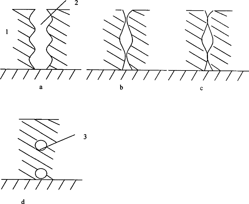
The invention discloses a post-processing method for reducing the thermal conductivity of a ceramic thermal barrier coating based on the fact that a thermal barrier coating system is the alloy of yttria partially stabilized zirconia surface (YSZ) and anti-oxidation bonding layer MCrAlY, and the matrix is nickel-based superalloy. The surface is partially heated by a laser heater, a flame heater ora high frequency sensing heater, based on the principle of mass transfer and diffusion in solid material under high temperature, the shape change of open communicated pores and cracks in the ceramic surface of the thermal barrier coating is controlled to achieve limited closure without surface remelting or sintered density, thus realizing hindering heat transmission to the inner superalloy along the coating surface. The method solves the defects of large coefficient of thermal conductivity and worse heat insulation effect of the thermal barrier coating in the prior art and does not damage excellent performance of the original coating. On the premise of not changing the thermal barrier coating material, the post-processing method has the advantages of simple process and high production efficiency.

Description

technical field [0001] The invention relates to a post-treatment technology of a thermal barrier coating, in particular to a post-treatment method of a ceramic thermal barrier coating used for gas turbine hot end parts such as combustion chambers and turbine blades. Background technique [0002] In order to reduce the fuel consumption of aviation gas turbines, increase the thrust-to-weight ratio and flow ratio, and develop aviation power technology, the inlet temperature of gas turbines must be increased. At present, the gas temperature and pressure in the combustion chamber are constantly increasing, and the gas temperature is close to 2000K. The limit performance of traditional superalloys can no longer serve at such a high temperature. Therefore, it is difficult to meet the working requirements of gas engines only by the alloy itself. In order to adapt to the harsh working conditions of the turbine, the ceramic thermal barrier coating technology was developed. In 1976, th...

Claims


Application Information

Patent Timeline
Patent Type & Authority Patents(China)
IPC IPC(8): C04B41/80
Inventor 梁工英张晖丁秉钧王铁军虞烈
Owner XI AN JIAOTONG UNIV
Learn More