Wireless remote control coreless invisible lock

A wireless remote control, invisible technology, applied in the direction of building locks, lock applications, electric registration locks, etc., can solve the problems of insecurity, damage to the lock cylinder, exposed lock cylinder and key hole, etc., to achieve powerful functions, flexible installation, The effect of high anti-theft performance

Inactive Publication Date: 2009-02-04
李庚信
View PDF0 Cites 1 Cited by
  • Summary
  • Abstract
  • Description
  • Claims
  • Application Information

AI Technical Summary

Problems solved by technology

[0002] Existing anti-theft locks almost all use magnetic card locks, IC card locks, induction card locks, infrared locks, digital keypad locks, fingerprint locks or eye mask locks, etc., but they are all unlocking tongues, and there is only one unlocking action mode. That is, there is only one mechanical action, which controls the expansion and contraction of the lock tongue (lock bolt), and the lock cylinder and the lock hole are exposed, which is easy for criminals to use the master key or directly destroy the lock cylinder to provide opportunities to commit crimes
There are also unlocked by remote control, such as locks with RF wireless remote control, but the remote control has no password setting, no remote control logout and other functions, once the remote control is stolen, it will be unlocked by others, which is extremely unsafe, and the traditional remote control Most of them adopt a one-way communication method, that is, the remote control only transmits a signal to the lock body, whether the lock body has received it, or whether it has been unlocked, but does not know

Method used


Image

  • Wireless remote control coreless invisible lock
  • Wireless remote control coreless invisible lock
  • Wireless remote control coreless invisible lock

Examples


Embodiment approach 1

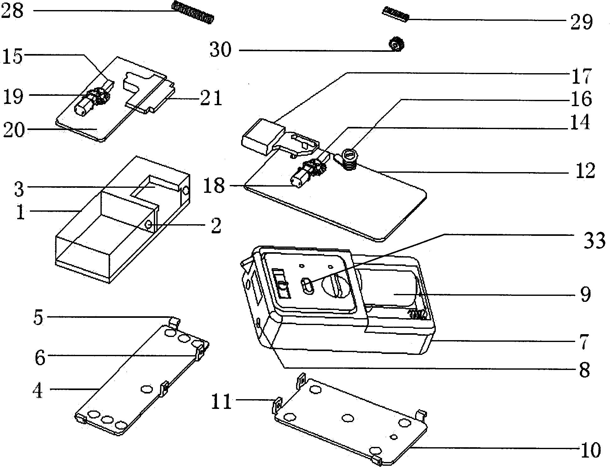
[0037] according to figure 1 As shown, when the lock body 12 is provided with one motor and the lock base 20 is provided with one motor, the unlocking process is as follows: the motor A18 of the lock body 12 works, drives the bevel gear A14 with a lever, moves the dead bolt 17, and makes the dead bolt 17 After reaching the designated position, it will automatically stop to achieve the purpose of opening / closing. If the motor A18 fails to operate, it will automatically start the action system of the lock seat 20, and the motor B19 will work. The motor B19 will drive the bevel gear B15 with the lever to move the lock seat Move the baffle 21 to make the lock seat move the baffle 21 to the position of opening / closing the seat frame, so as to achieve the purpose of opening / closing.

Embodiment approach 2

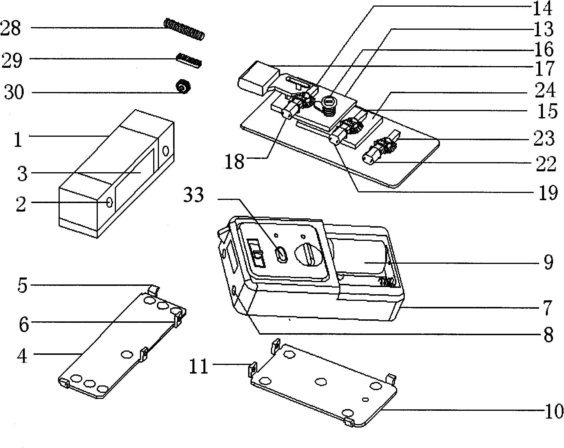
[0039] according to figure 2 As shown, when the lock body 12 is provided with 3 motors and the lock base 20 is provided with 0 motors, the unlocking process is as follows: the motor A18 of the lock body 12 works, drives the bevel gear A14 with a lever, moves the dead bolt 17, and makes the dead bolt 17 After reaching the designated position, it will automatically stop to achieve the purpose of opening / closing. When the motor A18 fails to operate, the MCU will automatically start the motor B19 to work, and the motor B19 will drive the bevel gear B15 with the lever to move the lock body. The carriage A13 drives the motor A18 to move together with the lock tongue 17, so that the lock tongue 17 reaches the designated position and completes the opening / closing action. If the motor B19 still fails, the MCU automatically starts the motor C22 to work, and the motor C22 drives the bevel gear C23 with a lever , move the lock body carriage B24, the motor A18 and the motor B19 are driven...

Embodiment approach 3

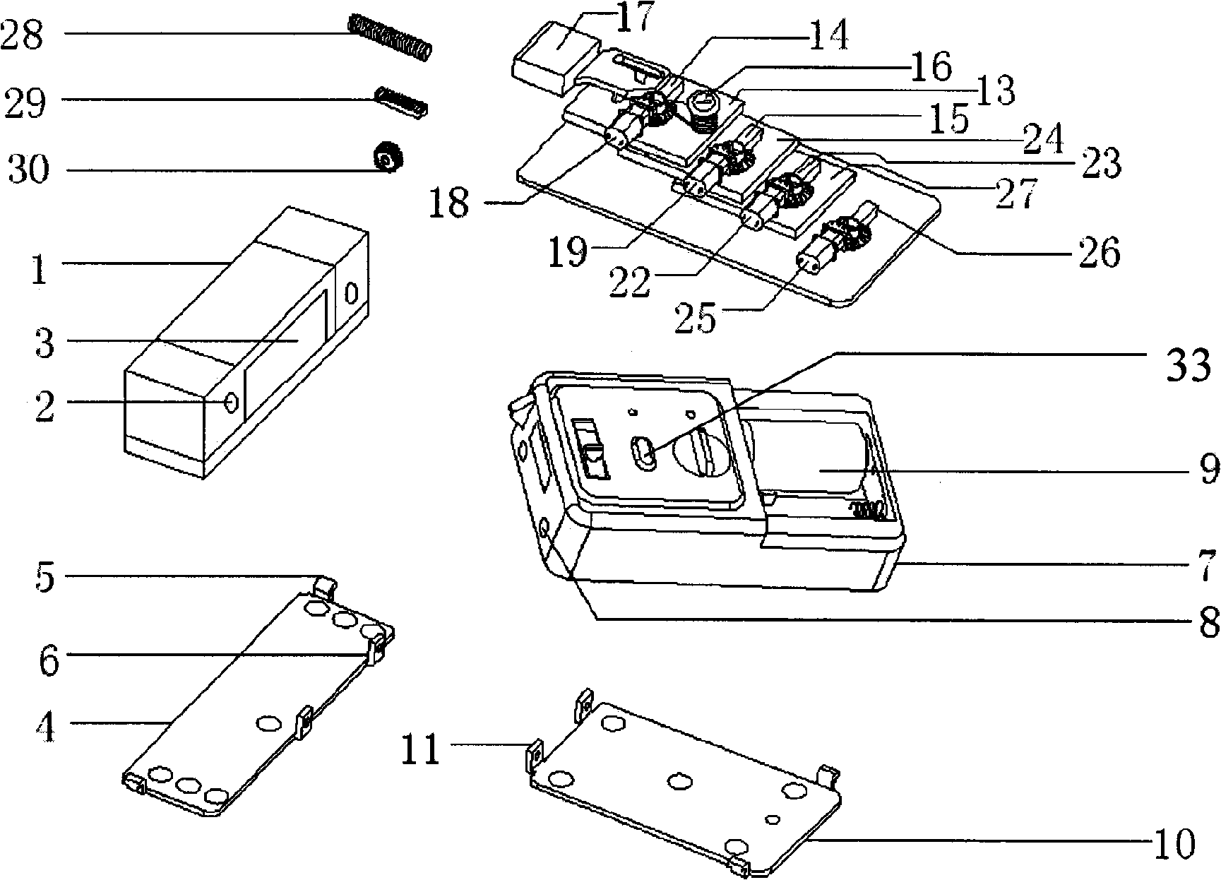
[0041] according to image 3 As shown, when the lock body 12 is provided with 4 motors and the lock base 20 is provided with 0 motors, the unlocking process is as follows: the motor A18 of the lock body 12 works, drives the bevel gear A14 with a lever, moves the dead bolt 17, and makes the dead bolt 17 After reaching the designated position, it will automatically stop to achieve the purpose of opening / closing. When the motor A18 fails to operate, the MCU will automatically start the motor B19, and the motor B19 will work, driving the bevel gear B15 with a lever, moving the lock body drag plate A13, and the lock The body drag plate A13 drives the motor A18 to move together with the lock tongue 17, so that the lock tongue 17 reaches the designated position to achieve the purpose of opening / closing. If the action of the motor B19 still fails, the MCU automatically starts the motor 22C, and the motor C22 works to drive the belt lever. Bevel gear C23, moving the lock body carriage ...


PUM


Abstract

The invention discloses a wireless remote-control hidden lock which belongs to the field of lock and is structured by including a lock body, a lock holder, a remote controller, a telephone control system and a power part. The lock body is closely fixed on the bottom plate of the lock body and is externally provided with the shell of the lock body; a communicating mode of FSK or ASK or Bluetooth technology of single-directional or bi-directional RF is adopted by the remote-controller. The invention transmits a signal to the lock body by the remote controller; the lock body after receiving the signal returns the signal to the remote controller to communicate information that whether a lock bolt is opened or not until the lock bolt is opened; while when lock bolt is failed to be opened, the remote controller can automatically switch to a spare system to move the carriage of the lock body or the carriage of the lock holder to drive the lock bolt to open the lock; if the lock can not be opened still, manual operation can be selected to open the lock until the lock is opened. The wireless remote-control hidden lock is provided with a plurality of sets of independent unlocking modes, can adopt remote unlocking, telephone unlocking, fire control unlocking, manual unlocking and has the advantages of high automatization degree, good anti-theft performance, humanized design and high practicability; besides, the wireless remote-control hidden lock is a necessary assistant for broad families as well as enterprises and institutions.

Description

technical field [0001] The invention relates to a lock structure, in particular to a wireless remote control coreless invisible lock which can be remotely controlled, has high safety and has a wide application range. Background technique [0002] Existing anti-theft locks almost all use magnetic card locks, IC card locks, induction card locks, infrared locks, digital keypad locks, fingerprint locks or eye mask locks, etc., but they are all unlocking tongues, and there is only one unlocking action mode. That is, there is only one kind of mechanical action, which controls the expansion and contraction of the dead bolt (lock bolt), and the lock cylinder and the lock hole are exposed, which is easy for criminals to use the master key or directly destroy the lock cylinder to provide opportunities to commit crimes. There are also unlocked by remote control, such as locks with RF wireless remote control, but the remote control has no password setting, no remote control logout and o...

Claims


Application Information

Patent Timeline
Patent Type & Authority Applications(China)
IPC IPC(8): E05B49/00
Inventor 李庚信
Owner 李庚信
Why Eureka
Try Eureka