
Well cleanout shunt

A diverter and positive washing technology, applied in the field of well flushing diverter, can solve the problems of increasing operating cost, large amount of well flushing fluid, long well flushing time, etc., and achieves the effects of stable work, shortened operating time and convenient use.

Active Publication Date: 2009-02-04
PETROCHINA CO LTD
View PDF0 Cites 4 Cited by
  • Summary
  • Abstract
  • Description
  • Claims
  • Application Information

AI Technical Summary

Problems solved by technology

[0002] Heavy oil wells need to be regularly hot-washed to remove wax and impurities in the pump that affect the work of the pump valve. Usually, when backwashing is used, part of the heat of the well-washing fluid is directly transferred to the direction of the casing, and the loss is serious. The amount of well-washing fluid is large and the well-washing It takes a long time; for oil wells with low reservoir pressure, when backwashing the well, a large part of the well flushing fluid leaks into the reservoir without entering the pump, and this large part of the well flushing fluid will cause serious damage to the reservoir due to poor compatibility with the reservoir; for special The well must be tripped and tripped multiple times, which increases operating costs

Method used


Image

  • Well cleanout shunt

Examples


Embodiment

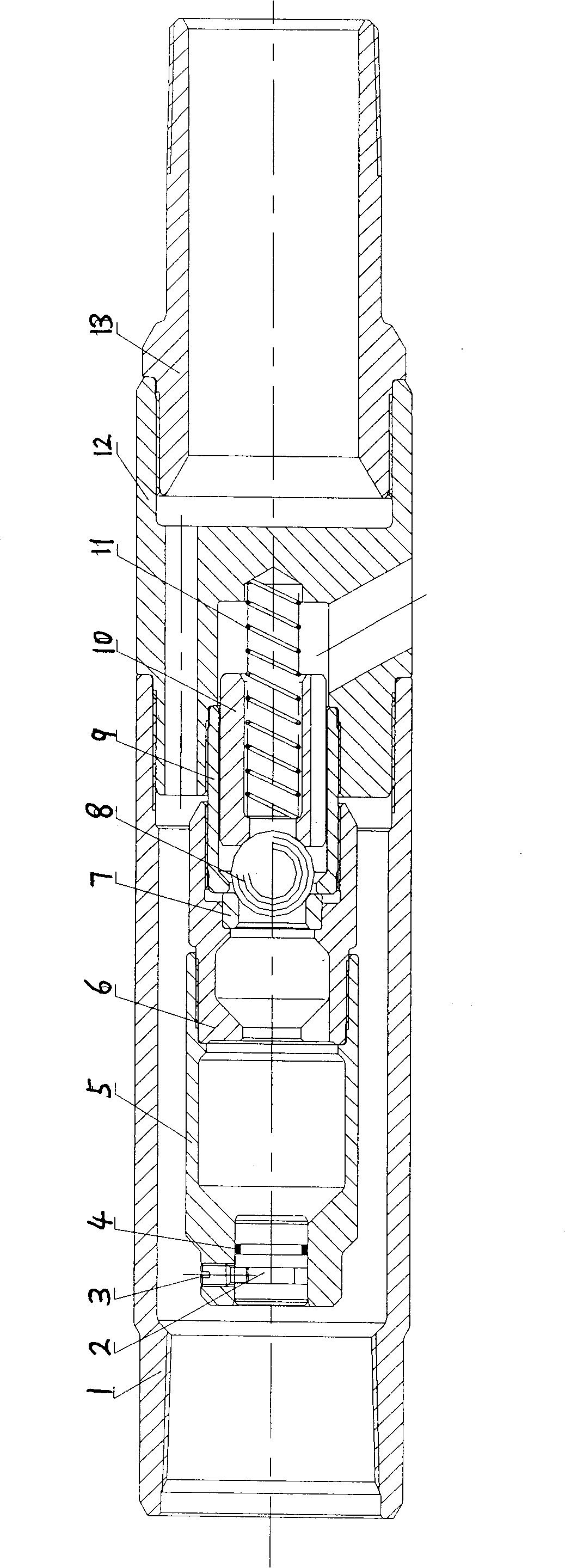
[0010] As shown in the figure, the present invention consists of an outer sleeve 1, a piston 2, a shear nail 3, an O-ring 4, a sealing joint 5, a valve cover 6, a valve seat 7, a valve ball 8, a pair of wires 9, and a spring sleeve 10) Composed of spring 11, shunt joint 12 and lower joint 13, the outer sleeve 1 is connected with the outer diameter of the upper end of the shunt joint 12, the lower end of the shunt joint 12 is connected with the lower joint 13, and the inner diameter of the upper end of the shunt joint 12 is sequentially connected upwards to the wire 9 and the valve cover 6 , the sealing joint 5, the piston 2 is fixed in the inner air above the sealing joint 5 by the shear nail 3, the gap between the sealing joint 5 and the piston 2 is an O-shaped sealing ring 4, and the wire 9 and the valve cover 6 are pressed against the valve seat 7, The valve ball 8 is under the valve seat 7 in the middle of the pair of wires 9. The spring sleeve 10 that can slide longitudina...


PUM


Abstract

A well direct-washing current divider consist of an outer sleeve 1, a piston 2, a shear pin 3, an O-shaped seal ring 4, a seal joint 5, a valve hood 6, a valve seat 7, a valve ball 8, a sewing wire, a spring sleeve 10, a spring 11, a current dividing joint 12 and a lower joint 13. As the well direct-washing current divider is fixed on the inner space at the upper part of the seal joint by the shear pin through the piston, the valve ball is arranged on the lower surface of the valve seat in the middle of the sewing wire, the lower surface of the valve ball is the spring sleeve which can slide longitudinally and the lower end of the spring sleeve is the spring; when washing directly, a well-washing liquid floating from a pump flows into the valve hood through the inner hole of the seal joint to open the valve ball and then flows into the well washing channel of a shunting joint through an annular flow passage between the sewing wire and the spring sleeve and enters into the annular space of an oil tube and a bushing as well as returns to the ground finally. When the oil is pumped, the valve ball is closed under the effect of the spring; the liquid in the annular space of the oil tube and the bushing can not enter into an oil pumping tubing string, thus preventing the well washing liquid from leaking into an oil layer, improving the well washing quality and shortening the operation time. The well direct-washing current divider of the invention is reasonably designed, conveniently used, stably works and is very suitable for being popularized and applied on spot.

Description

Technical field: [0001] The invention relates to a downhole tool used in oil field production, in particular to a positive flushing diverter. Background technique: [0002] Heavy oil wells need to be regularly hot-washed to remove wax and impurities in the pump that affect the work of the pump valve. Usually, when backwashing is used, part of the heat of the well-washing fluid is directly transferred to the direction of the casing, and the loss is serious. The amount of well-washing fluid is large and the well-washing It takes a long time; for oil wells with low reservoir pressure, when backwashing the well, a large part of the well flushing fluid leaks into the reservoir without entering the pump, and this large part of the well flushing fluid will cause serious damage to the reservoir due to poor compatibility with the reservoir; for special The well must be tripped and tripped multiple times, which increases operating costs. Invention content: [0003] The purpose of t...

Claims


Application Information

Patent Timeline
Patent Type & Authority Applications(China)
IPC IPC(8): E21B37/00E21B34/06E21B36/00
Inventor 徐兆强刘秀兰高艳云刘东菊王明军刘瑞珍
Owner PETROCHINA CO LTD
Learn More