Process for positioning spatial position of pipe mouth based on vision

A technology of spatial position and positioning method, applied in the field of image processing and pattern recognition, which can solve the problems of low robot execution efficiency, low degree of automation, and errors.

Inactive Publication Date: 2009-02-04
HUNAN UNIV
View PDF0 Cites 35 Cited by
  • Summary
  • Abstract
  • Description
  • Claims
  • Application Information

AI Technical Summary

Problems solved by technology

Most of the traditional methods are to manually calculate the position of the nozzle and then control the movement of the robot. The execution efficiency of the robot is low, it is easy to cause errors, and the degree of automation is low.

Method used


Image

  • Process for positioning spatial position of pipe mouth based on vision
  • Process for positioning spatial position of pipe mouth based on vision
  • Process for positioning spatial position of pipe mouth based on vision

Examples


Embodiment 1

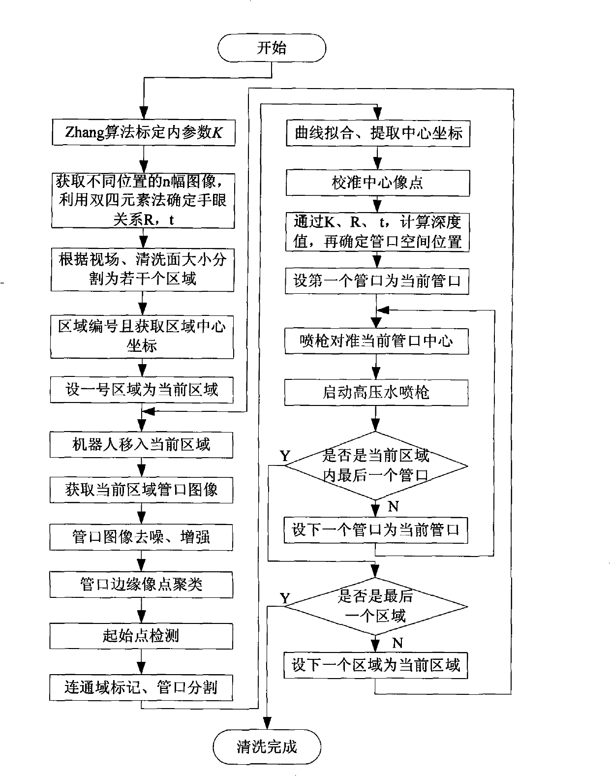
[0061] Place the underwater cleaning robot in harsh environments such as large power plants and steel mills to perform nozzle cleaning tasks. The robotic arm of the robot is equipped with a vision system, which senses the nozzle to be cleaned and calculates the corresponding nozzle space Location. According to the size of the work site and the effective field of view of the camera, the working surface is divided into areas by offline manual calculation, and the rough positioning is divided into blocks to control the movement of the robot. When the robot moves to a certain position of the rough positioning, the camera observes the nozzle in the local area. distribution, using the vision system to precisely locate the position of each nozzle.

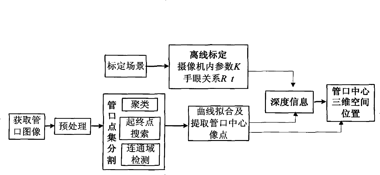
[0062] The process principle block diagram of the present invention is as follows figure 1 Firstly, the hand-eye relationship of the robot is calibrated off-line, and the geometric mapping relationship between the 2D pixel coordinates an...


PUM


Abstract

The invention proposes a pipe orifice spatial position positioning method based on vision; the positioning method mainly includes the steps: 1) the robot hand-eye relation is calibrated; the calibration and conversion of a plurality of coordinate systems determine the geometrical mapping relation of the 2D pixel coordinates and the three-dimensional spatial scene; 2) the image of the condenser is obtained; the pipe orifice image point set is segmented and the pipe orifice curve is fitted to extract the center image point of each pipe orifice; 3) the depth information is computed and the actual position of the pipe orifice space is further determined according to the image point of the pipe orifice center and the parameters of K, R and t. when the underwater cleaning robot starts the high-pressure water-spraying gun to wash the pipe orifice, the method is adopted to assist the robot in searching and positioning the position of the pipe orifice, so as to enable the robot to realize the automatic positioning of the pipe orifice and finish the washing operation. The method can greatly improve the accuracy in the pipe orifice positioning for the robot, the automation degree of the robot which replaces humans to work, the operational performance and the environmental adaptability of the robot.

Description

technical field [0001] The invention belongs to the field of image processing and pattern recognition, and relates to a method for locating the spatial position of a nozzle based on vision. Background technique [0002] At present, from the automatic tracking of welds processed by large-scale mechanical equipment, precision assembly operations, automated production lines for food canning and pharmaceutical filling, automatic scrubbing of windows in high-rise buildings, to cleaning work in harsh environments, etc. Various automation applications Among them, the positioning of objects by robots is one of the key technologies in the process of robot operations. [0003] The use of laser sensors, vision sensors, etc. has been successfully applied in robotic systems, but it has not been able to provide a general, efficient and automated solution that meets the needs of modern society. In order to improve the robot's operating ability, degree of automation and adaptability to the...

Claims


Application Information

Patent Timeline
Patent Type & Authority Applications(China)
IPC IPC(8): G06T7/00G06K9/00G01C11/00
Inventor 王耀南许海霞朱江余洪山袁小芳宁伟陈维孙程鹏杨民生
Owner HUNAN UNIV
Why Eureka
Try Eureka