Combined rotor structure of permanent magnet wind power generator

A technology for wind turbines and combined rotors, which is applied in the shape/style/structure of the magnetic circuit, synchronous motors with static armatures and rotating magnets, and rotating parts of the magnetic circuit, etc., which can solve problems such as poor placement of permanent magnets , to achieve the effect of light weight, good shock resistance and cost reduction

Inactive Publication Date: 2009-02-04
SHENYANG POLYTECHNIC UNIV
View PDF0 Cites 20 Cited by
  • Summary
  • Abstract
  • Description
  • Claims
  • Application Information

AI Technical Summary

Problems solved by technology

[0003] In order to solve the shortcomings of the above devices, the present invention provides a rotor structure that can be applied to permanent magnet wind p

Method used


Image

  • Combined rotor structure of permanent magnet wind power generator
  • Combined rotor structure of permanent magnet wind power generator
  • Combined rotor structure of permanent magnet wind power generator

Examples


Embodiment Construction

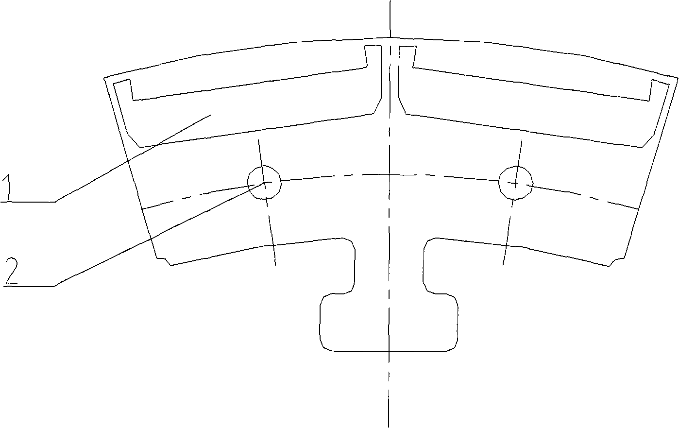
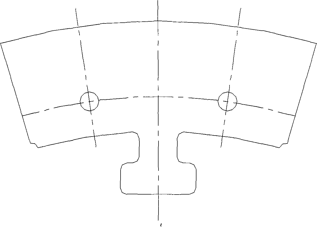
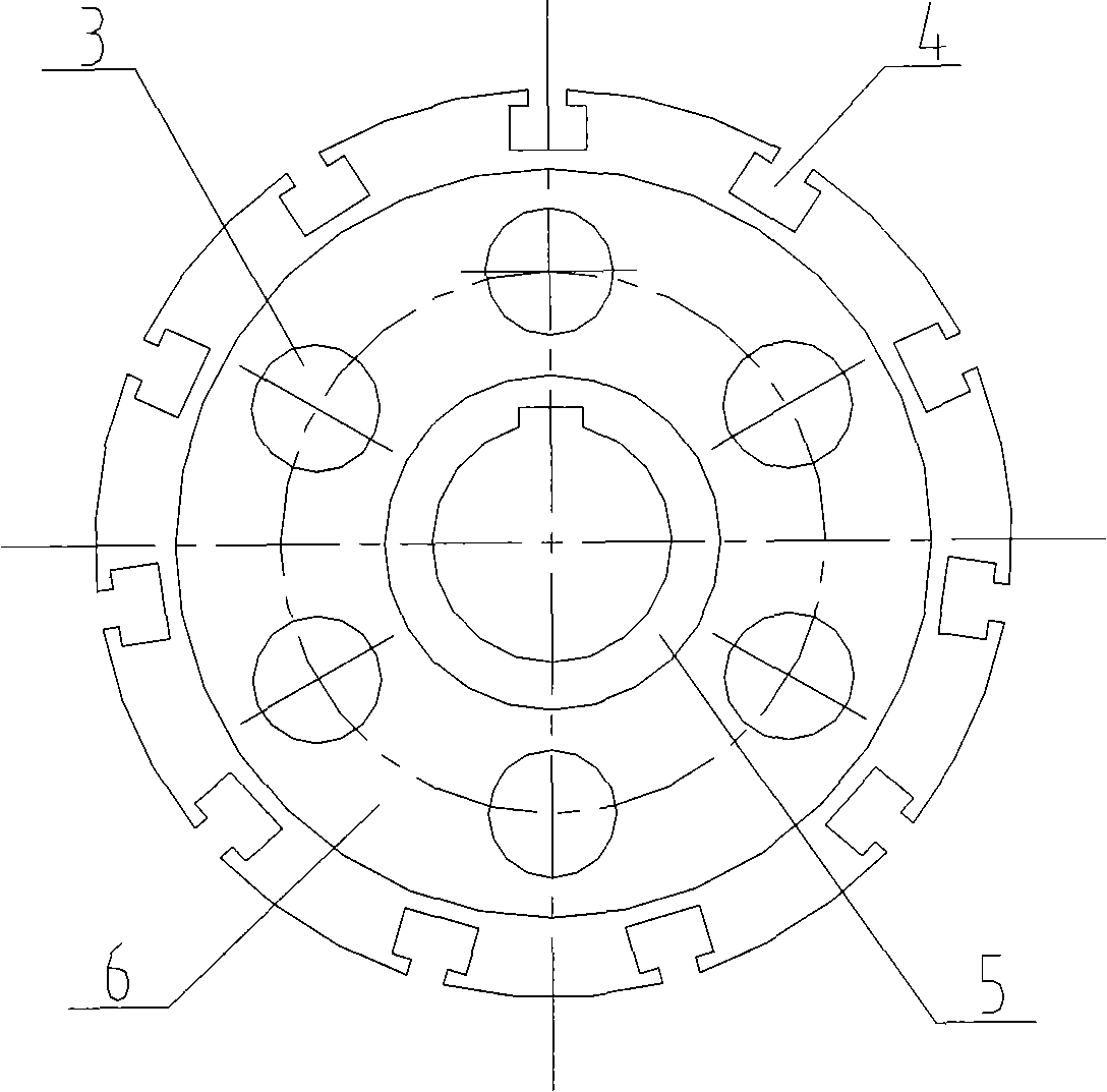
[0016] A kind of permanent magnet wind power generator, comprises rotor, stator and shaft, described rotor comprises rotor support, magnetic pole and permanent magnet 7, is provided with dovetail groove 4 on the side wall of cylindrical rotor support, and magnetic pole is installed in dovetail groove 4, The magnetic poles are formed by stacking sector-shaped punches, and each punch is provided with symmetrical permanent magnet slots 1, and the permanent magnets are put into the permanent magnet slots 1. The dovetail slots 4 are evenly distributed on the side wall of the rotor support. Rotor weight-reducing holes 3 are evenly distributed along the circumferential direction at the positions of the supporting spokes 6 of the rotor bracket. The permanent magnet slot 1 is boat-shaped, and the permanent magnet is placed in the hull of the permanent magnet slot 1. The permanent magnet slot is 0.1mm to 0.3mm larger than the permanent magnet in length and width, and the two adjacent pe...


PUM


Abstract

The invention provides a combined rotor structure of a permanent magnet wind power generator, which belongs to the technique field of permanent magnet wind power generator, and adopts the technical proposal that: fan-shaped punching sheets are laminated to form a magnetic pole, a permanent magnet is inserted into a permanent magnet groove reserved on the fan-shaped magnetic pole along the axial direction of a motor, and an air magnetic shield bridge is formed in the fan-shaped magnetic pole, the whole magnetic pole is inserted into a dovetail groove of a rotor support along the axial direction, rotor lightening holes are evenly distributed at supporting spoke positions along the circumferential direction, both sides of the magnetic pole are added with a magnetic pole pressing plate respectively, the magnetic pole and the magnetic pole pressing plates are fastened together by bolts through location holes, and location wedges are wedged into gaps of the magnetic pole and the support from both sides along the axial direction to ensure that the magnetic pole and the support are combined into one body, so the magnetic pole with the built-in permanent magnet can be completed.

Description

technical field [0001] The invention relates to the technical field of generators, in particular to a combined rotor structure of a permanent magnet wind power generator. technical background [0002] The permanent magnet synchronous generator rotor structure can be divided into built-in type and surface type according to the permanent magnet installation method. The built-in type is to slot the inside of the rotor to insert the permanent magnet into the rotor along the axial direction. Adhesive to the surface of the rotor yoke or press the permanent magnet on the surface of the rotor yoke with a non-magnetic dovetail pressure piece. From a structural point of view, the two installation methods have their own advantages, but the direct drive wind turbine requires a lower speed, so It is required to increase the number of stages of the generator. Usually, the installation method of the built-in permanent magnet is not effective when the number of poles of the motor is large, ...

Claims


Application Information

Patent Timeline
IPC IPC(8): H02K1/27H02K1/28H02K21/12H02K21/02
CPCH02K2213/12
Inventor 唐任远安忠良马鑫毕海涛
Owner SHENYANG POLYTECHNIC UNIV
Why Eureka
Try Eureka