Link packet drop rate control method and system based on terminal

A packet loss rate and link technology, applied in transmission systems, digital transmission systems, electrical components, etc., can solve problems such as lack of good support and reduced program work efficiency, to avoid waste and improve work efficiency. Effect

Active Publication Date: 2009-02-04
CHINA UNITED NETWORK COMM GRP CO LTD +1
0 Cites 11 Cited by

AI-Extracted Technical Summary

Problems solved by technology

However, RTP and RTCP only support some multimedia audio and video services, and other services such as audio and video services or file transfer services independently developed by some instant messaging software are not well supported; at the same time, algorithms based on RTP/RTCP protocols are usually u...

Method used

[0045] c. According to the detection results provided in b, the data packets are scheduled according to the network conditions of different links, so as to achieve a reasonable allocation of network resources.
[0077] According to the above-mentioned method of the present invention, w...

Abstract

The invention relates to a control method for link packet discard rate based on the terminal and a system thereof. The method comprises: a packet which is transmitted from a local host computer to a remote host computer is acquired at the network layer, and the IP address of the remote host computer is recorded; the local host computer transmits a detection packet to the remote host computer according to the IP address of the remote host computer, the remote host computer obtains the average discard packet intervals of the current link according to the detected data and returns the average discard packet intervals of the current link to the local host computer; the local host computer obtains the network status rank of the current link according to the average discard packet intervals of the current link and the preset network status rank quantization table, and adjusts the link packet discard rate of the current link according to the network status rank of the current link and the preset packet discard rate distribution table; and the network status rank quantization table contains the corresponding relation of the average discard packet intervals and the network status rank. The invention can avoid the waste of network resources, and effectively improve the working efficiency of network.

Application Domain

Technology Topic

Ip addressNetwork layer +5

Image

  • Link packet drop rate control method and system based on terminal
  • Link packet drop rate control method and system based on terminal
  • Link packet drop rate control method and system based on terminal

Examples

  • Experimental program(1)

Example Embodiment

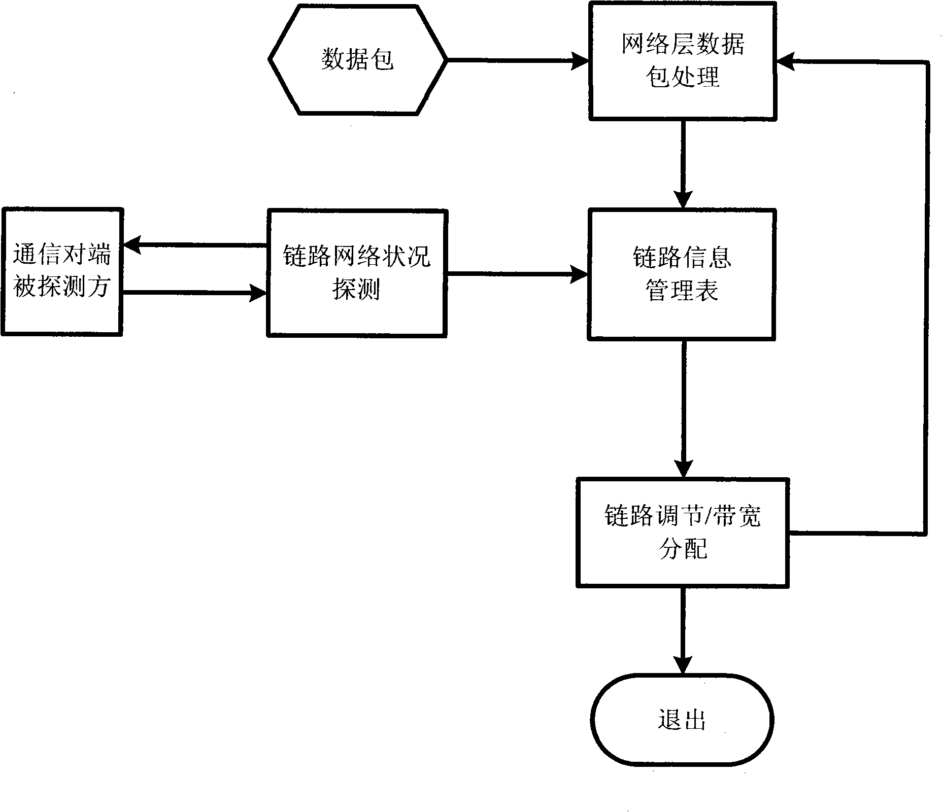
[0041] The overall process of the present invention is as figure 1 As shown, the data packet is intercepted first, and then relevant information is extracted to establish the link information management table; at the same time, the network status is continuously detected on the communication link, and the link packet loss rate is adjusted according to the detection result, and Update the link information management table in time.
[0042] When the local communication host and the remote communication host perform multimedia communication, perform the following steps:
[0043] a. At the network layer, the data packets sent from the local host to the remote host are intercepted, and the link information management table is established to manage the data packets.
[0044] b. Perform real-time network link status detection during the above communication process, and return the detection result.
[0045] c. According to the detection results provided in b, data packets are scheduled according to the network conditions of different links, so as to achieve a reasonable allocation of network resources.
[0046] According to the above method of the present invention, the step a includes:
[0047] a1. The local host intercepts data packets sent to the remote host at the network layer.
[0048] a2. Analyze the data packet sent to the remote host according to the characteristics of the network layer data packet, extract the IP address information and use the IP address to distinguish different communication links.
[0049] a3. Approximately count the bandwidth occupied by the current link according to the size of the data packet.
[0050] a4. Establish a link information management table based on different communication links, the content is as follows:
[0051] Node number
[0052] The link packet loss rate refers to the ratio of the number of lost data packets in the link transmission to the transmitted data packets. The packet loss rate in this method specifically refers to the loss of a certain link data packet for bandwidth allocation. Packet limit, so as to achieve the purpose of bandwidth control.
[0053] a5. Fill in the relevant information in a2 and a3 into the communication link information management table.
[0054] The step b includes:
[0055] b1. The local host is the client (detector), and respectively sends UDP detection data packets to the remote host (detected party), and the detection packet interval is 200ms.
[0056] For each communication host in the current network environment, it is actually a client and a server. That is, at this time, the remote host is also sending detection data packets to the local host.
[0057] b2. The remote host is the server (the detected party), which receives the detection data packet, and calculates the average packet loss interval of the current communication link based on the serial number and other related information contained in the data packet.
[0058] The number of packet loss intervals refers to the number of correctly sent data packets between two consecutive packet loss events. The occasional packet loss interval obviously cannot reflect the network status. Therefore, we introduced the concept of average packet loss interval, which is simply a weighted average of the number of packet loss intervals in the most recent period to obtain an average packet loss situation that can reflect the recent network conditions.
[0059] b3. The remote host counts the detection results, and returns the calculation results to the local host (detector) periodically (for example, every 2.5s).
[0060] b4. The local host terminal judges the current link network status according to the detection result in b3:
[0061] b4.1) If the average number of packet loss intervals is greater than or equal to the threshold ThresF1, the current communication link network status level is I, which is described as Perfect;
[0062] b4.2) If the average packet loss rate interval is greater than or equal to the threshold ThresF2 and less than ThresF1, the current communication link network status level is II, which is described as Good;
[0063] b4.3) If the average packet loss rate interval is greater than or equal to the threshold ThresF3 and less than ThresF2, the current communication link network status level is III, which is described as Middle;
[0064] b4.4) If the average packet loss rate interval is greater than or equal to the threshold ThresF4 and less than ThresF3, the current communication link network status level is IV, which is described as Poor;
[0065] b4.5) If the average packet loss rate interval is less than the threshold ThresF4 and greater than or equal to 0, the current communication link network status level is V, which is described as Bad.
[0066] b5. Fill the above-mentioned network status level in the link information management table described in a4 according to the IP address, and perform regular update and maintenance every 2s.
[0067] The step c includes:
[0068] c1. Take the network status corresponding to the current time t as a reference, and periodically query the network status of the corresponding link in the link information management table with a period of 1s.
[0069] c2. If the network status corresponding to the next time is different from the time t, and the network status corresponding to this time remains unchanged for more than 3s, it is determined that the current network status has changed, and the link information management table is modified The network status level of the current link.
[0070] c3. Perform packet loss adjustment based on the network conditions in c2, and uniformly adjust the link packet loss rate of the link. The adjustment is mainly achieved by changing the packet loss rate of the corresponding link. For details, refer to the following packet loss rate allocation table:
[0071]
[0072] Each percentage number in the table refers to the change value of the link packet loss rate. In the present invention, the bandwidth control is mainly achieved by adjusting the packet loss rate. As shown in the above table, the corresponding numbers in the table where each row and column intersect in the table represent the packet loss intensity that should be adopted when the two network conditions change. The numbers in the table indicate the corresponding packet loss rate based on the current network conditions. Increase or decrease the percentage value of the packet loss rate. (The default is zero packet loss when in network condition I) It is emphasized here that because the priority order of the network level in the present invention is sequentially reduced from IV, when the network condition changes from a high-level network to a low-level network condition, packet loss in the table The value of rate adjustment is the percentage value of the increase in the packet loss rate, that is, the intensity of packet loss should be increased at this time; otherwise, the intensity of packet loss should be reduced. For example, if the current network status changes from network status I to network status III, then according to the data in the table, the link packet loss rate will be adjusted from zero to 20%, and the system will intercept the link on the network layer. According to the random packet loss method, 20% of the data packets are dropped on average, and the remaining data packets are allowed to continue, which means that the effective link bandwidth is reduced by about 20%; then, the network status changes from network status III to network status IV. According to the data in the table, the link packet loss rate will increase by 25% and adjust to 45%. In other cases, the same applies.
[0073] The above packet loss rate allocation table shows the correspondence between changes in network conditions and changes in the link packet loss rate. In order to achieve the above function, you can also directly record the change in the average packet loss interval and the link in the packet loss rate allocation table. The corresponding relationship between the changes in the packet loss rate, and then use the corresponding relationship to adjust the link packet loss rate to adjust the link packet loss rate of the current link. The packet loss rate allocation table is as follows:
[0074]
[0075] The percentage numbers in the above table also refer to the change value of the link packet loss rate. The corresponding number in the table where each row and column intersects in the table indicates that the average packet loss interval number changes between the two value ranges. The numbers in the table indicate the percentage value of the packet loss rate that should be increased or decreased based on the corresponding packet loss rate in the current interval. (When the average packet loss interval is in the interval [70, +∞], the default is zero packet loss.) There is also a concept of priority order similar to the above table, the difference is that the priority order decreases in order according to the value of the interval boundary point. Therefore, when changing from the previous interval to the next interval, the value of the packet loss rate adjustment in the table is the percentage value of the packet loss rate increase, that is, the intensity of packet loss should be increased at this time; otherwise, the intensity of packet loss should be reduced. Correspondingly, the network status in the link information management table should be replaced by the average packet loss interval.
[0076] The invention is applied to a communication host running on a Linux operating system platform in a heterogeneous network environment, such as figure 2 As shown, including IP core network, WLAN (wireless local area network), LAN (local area network) and WWAN (wireless wide area network), WLAN (wireless local area network), LAN (local area network) and WWAN (wireless metropolitan area network) and IP core network are respectively connected. Such as figure 2 As shown, the present invention is also applicable to the multimedia communication service process based on the IP core network in a heterogeneous network access environment. In the case of heterogeneous access methods, the bandwidth that the network can provide is different, but The above detection and adjustment methods involved in the present invention are still effective.
[0077] According to the above method of the present invention, we can detect the network status of each link in real time and distinguish it according to different levels. When the link network status changes, we can achieve communication services through effective adjustments. Quality assurance and reasonable and optimized allocation of resources.
[0078] The following provides a method for real-time and automatic adjustment of service quality for established multimedia communication processes in a heterogeneous network environment. This embodiment is applied to a multimedia communication service of audio and video data transmission running on a Linux operating system platform.
[0079] The network topology used in this embodiment is as image 3 Shown. User A accesses the network wirelessly (here assumed to be WLAN), user B also accesses the network wirelessly (here assumed also WLAN), and user C accesses the network through LAN. User A transmits audio, video or file data with users B and C through the IP core network. The solid line indicates the wired link being connected, and the lightning symbol indicates the wireless link.
[0080] In this embodiment, when the multimedia communication service is in progress, this method is used to manage the data packets sent by user A to users B and C and adjust the corresponding link packet loss rate. When the network conditions of users B and C change (such as image 3 As shown in, it may be a sudden increase in local business volume or network congestion caused by other reasons), the specific steps taken are as follows:
[0081] Step 1. The first is the interception and management of network layer data packets. The specific steps are as Figure 4 As shown, the data packet first arrives at the relevant protocol stack of the operating system before being sent out, and the relevant hook function provided by the operating system is used to intercept the data packet at the network layer, and at the same time complete the analysis of the data packet content and the establishment of the link information table And maintenance, and further control the outflow of data packets on the corresponding link; when the network status changes and the link packet loss rate adjustment is required (see the following step 3 for the scheme to determine whether the network status has changed), perform the link packet loss rate adjustment Adjust, control the outflow of data packets on each communication link after the link bandwidth is adjusted.
[0082] Step 2: Perform real-time detection of network conditions, the specific steps are as follows, as attached Figure 5 As shown, the client (detector) first sends detection packets to the server (detected party). The server listens to the detection packets on a specific port and counts and calculates the average packet loss interval of the current link. The results are fed back to the detecting party in time. After receiving the results, the detecting party will perform statistics on the results, and then quantify them into the network status level, and finally update the network status level in the link information table in time.
[0083] Step 3: Adjust the packet loss rate of the link according to the results obtained in Step 2, combined with changes in the network condition level. The specific steps are as follows, such as Figure 6 As shown, the system periodically queries the link information table, and continuously extracts the link network status level information in the link information table and compares it with the currently obtained network status level. If it finds the current time and the network status level in the link information table If the value is different, and Ts (T=3) remains unchanged, it can be confirmed that the network status has changed and the packet loss rate value in the related link information table can be updated immediately. At the same time, in step one, the corresponding link bandwidth can be adjusted according to the updated value at this time.
[0084] The above three steps are described in detail below:
[0085] 1) Use the mechanism provided by the Linux operating system to intercept audio and video data packets sent to users B and C at the network layer of the protocol stack corresponding to user A.
[0086] The data packet interception mechanism mentioned here mainly refers to the functional framework provided by the operating system to achieve data packet filtering/processing, such as Netfilter (network filter). The functions provided by these mechanisms temporarily intercept the data packets sent by user A to users B and C, combined with the following steps 2), 11), and 12). When the network status of the link changes, the The packet loss rate is restricted according to different links (IP addresses).
[0087] 2) Analyze data packets sent to hosts B and C, extract IP address information and use IP addresses to distinguish different communication links. In addition, approximate statistics on the bandwidth occupied by the current link according to the length of the data packet.
[0088] The approximate bandwidth value of the current link referred to here refers to the average value obtained by summing the sizes of all data packets in the same time and dividing by the time, the unit is B/s, and the time value taken here is 2s.
[0089] 3) Fill in the results obtained in the link information management table below. The content includes node number, IP address, link network status, current link bandwidth and link packet loss rate, among which network status and packet loss The starting data of the rate is the default value, and the accurate test value is obtained by combining the subsequent steps. As shown in the table below (the values ​​in the table are experimental results, for reference only)
[0090] Node code
[0091] CN1
[0092] The above table reflects the information of the two links currently communicating. In actual situations, the table will be updated regularly according to a certain period of time to update the IP address and number of the work maintenance node and the bandwidth content of the current link, as well as the test results. Maintain the network status level value and set the packet loss rate of the corresponding link. For details, refer to the link information management table given later.
[0093] 4) As the detection terminal, user A sends UDP (User Data Protocol) detection data packets to the designated ports (port number 9211) of users B and C under test, and the detection packet interval is 200ms.
[0094] For each communication host in the current network environment, it is actually a client and a server. That is, at this time, users of the detected parties B and C are also sending detection data packets to user A. The present invention only describes the detection process from the A-B and A-C directions, and the detection process in the B-A and C-A directions is omitted.
[0095] 5) Users B and C listen to port 9211 and receive the detection data packet, and then calculate the average packet loss interval of the current communication link according to the sequence number contained in the data packet, and then return the result to the designated port ( Port number 9212).
[0096] In the steps 4) and 5) mentioned above, ports 9211 and 9212 are system-specific ports. Port 9211 is used to listen and receive UDP detection data packets sent by the probe; port 9212 is used to receive feedback from the server. As a result of the detection, the use of the above-mentioned specific port can effectively mark and distinguish detection data packets from other multimedia communication service data packets.
[0097] 6) After user A receives the detection result, it extracts the average packet loss interval information in it, and then performs statistics to quantify it into the corresponding network condition level. The network condition level is quantified according to the following rules:
[0098] 6.1) If the average number of packet loss intervals is greater than or equal to the threshold ThresF1 (for example, 70), the current communication link network status level is I, which is described as Perfect;
[0099] 6.2) If the average packet loss rate interval is greater than or equal to the threshold ThresF2 (for example, 10) and less than ThresF1, the current communication link network status level is II, which is described as Good;
[0100] 6.3) If the average packet loss rate interval is greater than or equal to the threshold ThresF3 (for example, 3.5) and less than ThresF2, the current communication link network status level is III, which is described as Middle;
[0101] 6.4) If the average packet loss rate interval is greater than or equal to the threshold ThresF4 (1.0) and less than ThresF3, the current communication link network status level is IV, which is described as Poor;
[0102] 6.5) If the average packet loss rate interval is less than the threshold ThresF4 and greater than or equal to 0, the current communication link network status level is V, which is described as Bad.
[0103] The network condition level quantification table shows the corresponding relationship between the network condition level and the average packet loss interval, and the threshold unit is the number. The network status level quantification table is as follows:
[0104] Average packet loss interval (ALI)
[0105] 7) The above quantification levels are classified according to different communication links (IP addresses). After user A receives the average packet loss interval from user B for the first time, the current link network status level can be obtained. In step 3), the network status level value in the corresponding link information table is updated, and the network status level value in the link information table can also be updated after the network status level lasts for 3s.
[0106] 8) Such as image 3 As shown, it is assumed that the level value of the network condition of the link between users A and B at t1 is I, and the network detection process is in continuous progress. In addition, the link adjustment of user A will query the link network status level information in the link information table established in step 3) with a period of 1s, and compare it with the level value at the next moment.
[0107] 9) Assuming that the result obtained after network detection at t2 is III, and the link network status level value stored in the link information table is I, at this time we believe that the link status may have changed.
[0108] 10) Continue to perform network status detection. If from t2, the network status level value of the link has been III and lasted for 3s. At this time, we believe that the link network status has changed.
[0109] 11) Limit the packet loss rate of the link (A---B) whose network status level value changes from I to III, and update the link information management table, as shown in the following table, network status and link packet loss The value of the rate has been updated.
[0110] Node
[0111] serial number
[0112] 12) Perform the corresponding packet loss in the hook function mentioned in the previous step 1), thereby limiting the bandwidth of the current link. In this example, it is reduced by 20%, that is, the bandwidth occupied by the link is reduced by 20%.
[0113] 13) Repeat the process of steps 9), 10), 11), and 12). At t3, it is found that the current network status of this link has been restored, that is, the network status level value changes from III to I. At this time, we Perform the opposite operation, set the packet loss rate to zero, and restore the limit on the link bandwidth.
[0114] 14) Follow the same steps as 2)-13) between users A and C, image 3 The middle user C accesses the network through a wired way, and at t1 and t2 also undergoes a similar network status change process. In addition, the user may switch during the communication process, and the steps of detection and adjustment remain unchanged.
[0115] The present invention also provides another implementation manner. The packet loss rate allocation table indicates the relationship between the network condition level and the link packet loss rate, such as I---0, II---10%, III---20% , IV--45%, V---60%. After user A receives the detection result from B, he quantifies the detection result into a network condition level value, and then adjusts the chain directly according to the data in the packet loss rate allocation table The packet loss rate of the road link. The packet loss rate allocation table can also indicate the relationship between the average packet loss interval and the link packet loss rate, such as [70, +∞)---0, [10, 70)---10%, [3.5, 10) ---20%, [1.0, 3.5)---45%, [0, 1.0)---60%, according to the above method, after user A receives the detection result from B, it directly allocates the table based on the packet loss rate The data in the link can be adjusted to adjust the link packet loss rate, which can also achieve the purpose of adjusting the link bandwidth.
[0116] The invention supports both IPv4 and IPv6 network environments. Among them, the interception and management of data packets, real-time network detection, and link bandwidth adjustment are all developed in standard C language, so that users can conveniently process data packets at the network layer. The present invention makes good use of the characteristics of the mechanism, and at the same time combines the network detection of the transmission layer to complete the management of data packets and the adjustment of the packet loss rate of the communication link at the network layer.
[0117] Those skilled in the art can also make various modifications to the above content without departing from the spirit and scope of the present invention as determined by the claims. Therefore, the scope of the present invention is not limited to the above description, but is determined by the scope of the claims.

PUM

no PUM

Description & Claims & Application Information

We can also present the details of the Description, Claims and Application information to help users get a comprehensive understanding of the technical details of the patent, such as background art, summary of invention, brief description of drawings, description of embodiments, and other original content. On the other hand, users can also determine the specific scope of protection of the technology through the list of claims; as well as understand the changes in the life cycle of the technology with the presentation of the patent timeline. Login to view more.

Similar technology patents

Device and method for monitoring water purifier

ActiveCN104941305AReal Water Production EfficacyAvoid wastingReverse osmosisFiltration separationResidual chlorineTerminal unit
Owner:BEIJING DIWINET TECH CO LTD

Classification and recommendation of technical efficacy words

  • Avoid wasting
  • Improve work efficiency

Improved novel energy automobile charging device

Owner:XIAMEN YINLV JIEYUAN ENVIRONMENTAL PROTECTION TECH CO LTD

Full-automatic water-drill grinding and polishing machine

InactiveCN101758433AImprove work efficiencyFixture positioning is accurateEdge grinding machinesManipulatorEngineering
Owner:瑞安市天成包装机械有限公司
Why Eureka
Try Eureka