Tissue closure and tissue closing device

A technology of closing devices and closers, which can be used in surgical instruments, medical science, surgical nails, etc., and can solve the problems of difficult operation of living tissue closing devices

Active Publication Date: 2009-02-11
TERUMO KK
View PDF2 Cites 5 Cited by
  • Summary
  • Abstract
  • Description
  • Claims
  • Application Information

AI Technical Summary

Problems solved by technology

Therefore, the angle can change to an undesired direction, and the living tissue closure device is difficult to operate

Method used


Image

  • Tissue closure and tissue closing device
  • Tissue closure and tissue closing device
  • Tissue closure and tissue closing device

Examples


no. 1 example

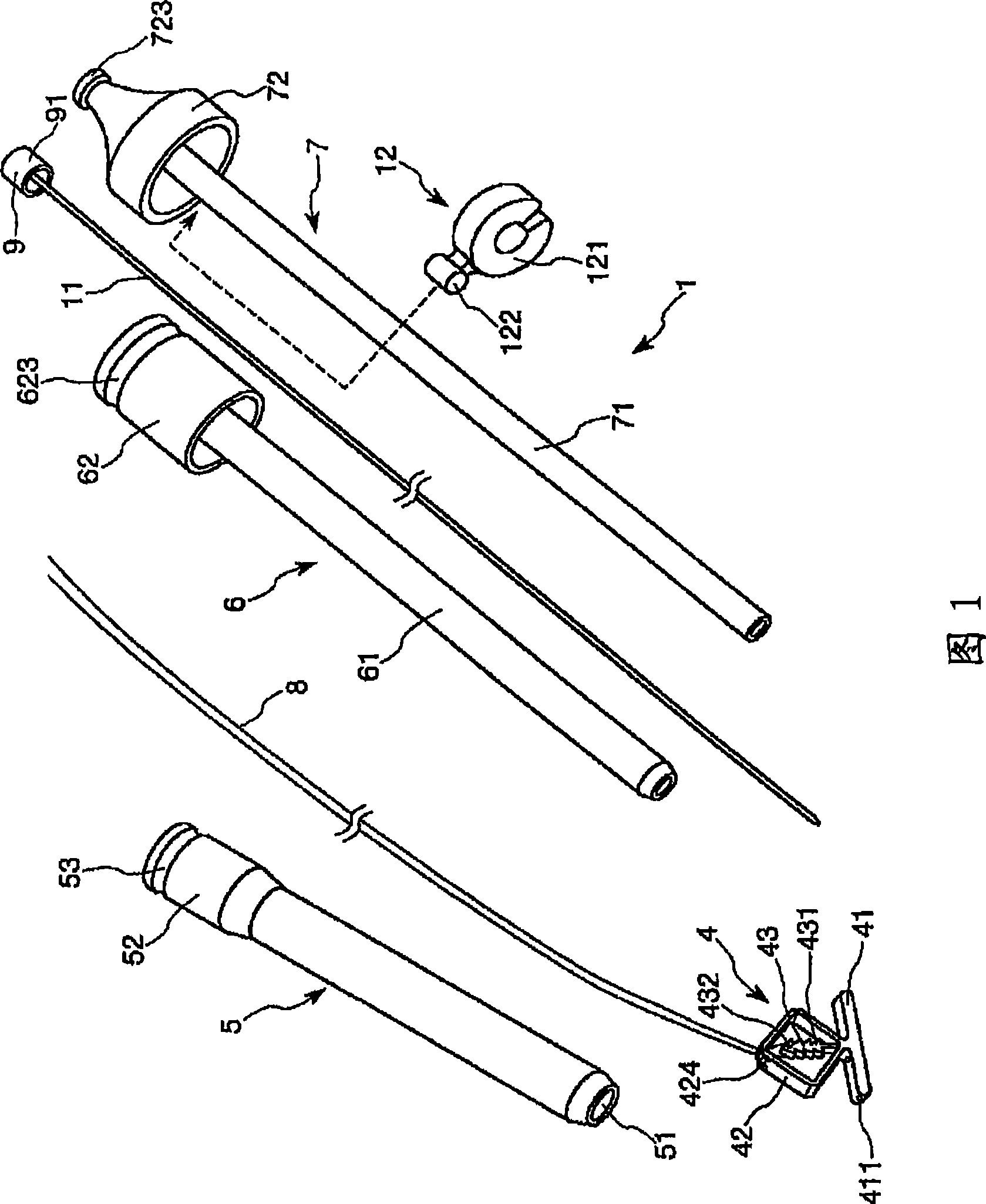
[0143] First, a first embodiment of the living tissue closing device of the present invention will be described.

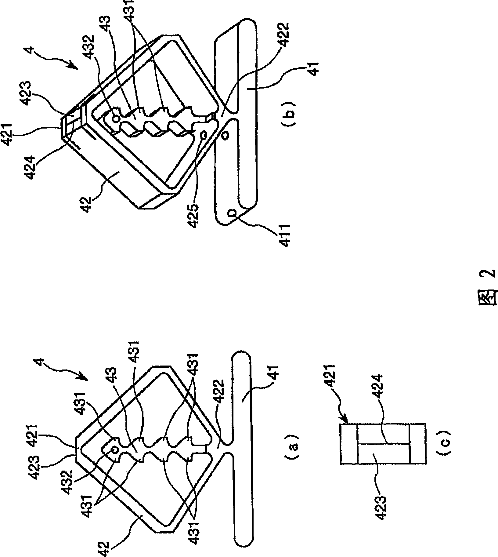
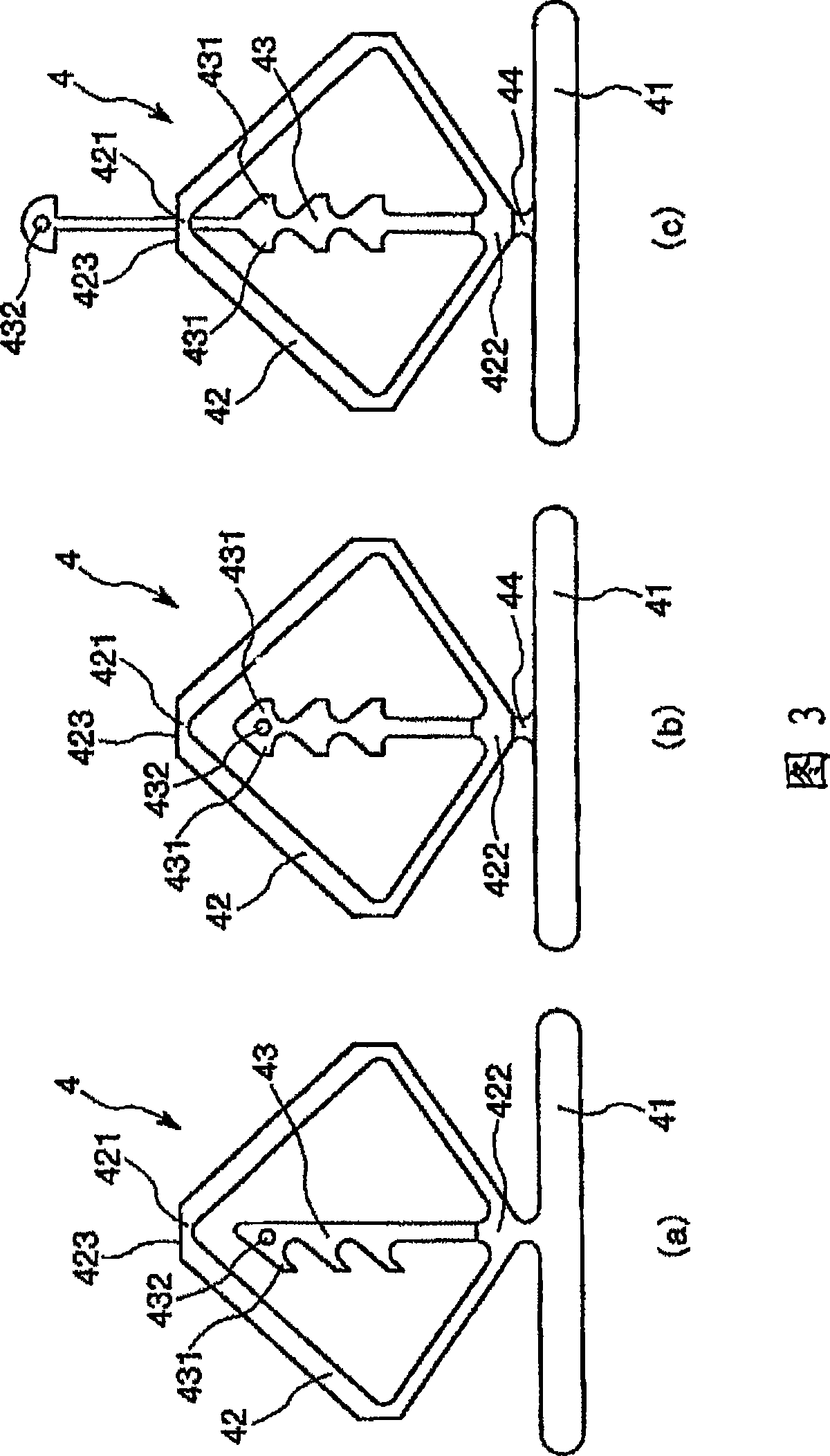
[0144] 1 is a perspective view showing a first embodiment of a living tissue closing device of the present invention; FIG. 2 is a front view (a), perspective view showing a living tissue closing device of the living tissue closing device shown in FIG. 1 Figure (b) and partial top view (c); Figure 3 (a), (b) and (c) are side views of different examples of the structure of the living tissue closure device in Figure 1 respectively; Figure 4 ( a) and (b) are front view and perspective view, respectively, of other different examples of the living tissue closer configuration of the living tissue closing device shown in FIG. 1; Figure 5 is a side view of another different example of the living tissue closer configuration of the living tissue closing device shown in FIG. 1; and FIGS. .

[0145] It should be noted that, for convenience of description, in Fig. 1 and Figs....

no. 2 example

[0228] Next, a second embodiment of the living tissue closing device of the present invention will be described.

[0229] 13 is a perspective view showing a second embodiment of the living tissue closing device of the present invention; FIG. 14 is a perspective view showing a living tissue closer of the living tissue closing device shown in FIG. 13; Figure 15 is another example of the configuration of the living tissue closer of the living tissue closing device shown in FIG. 13; and FIGS. 16 and 17 are sectional views showing the operation (action) of the living tissue closing device shown in FIG.

[0230] It should be noted that in FIG. 14 the propulsion tube 7 is schematically shown by dashed lines.

[0231] In addition, for convenience of description, in FIGS. 13 , 16 and 17 , the lower left side is referred to as "distal end", and the upper right side (hand side) is referred to as "proximal end". In addition, in FIGS. 14 and 15, although the upper side of the living tiss...

no. 3 example

[0258] A third embodiment of the living tissue closing device of the present invention will be described below.

[0259] Figure 18 is a perspective view showing a third embodiment of the living tissue closing device of the present invention; Figure 19 yes Figure 18 A perspective view of the action (operation) of the tissue closure device shown in , where Figure 19 The deformed part of (a) is in a closed state along the vertical direction, Figure 19 The deformed portion of (b) is in a state contained in the covering tube, and Figure 19 (c) is the state in which the front end of the covering tube is pressed into the blood vessel; and Figure 20 yes Figure 18 A perspective view of the action (operation) of the tissue closure device shown in , where Figure 20 (d) is a state in which the sealing part is rotated, Figure 20 (e) is a state in which the covering tube is rotated 180 degrees to cover the sealing part, Figure 20 (f) is a state where the clip is pulled ou...


PUM


Abstract

A living body tissue closing device 1 includes an elongated body element 2, a clip (living body tissue closure) 4 for closing a wound hole which penetrates a living body tissue membrane, and a thread 8. The body element 2 includes a sheath 5, and elongated feeding and deformation means 3. The elongated feeding and deformation means 3 includes a covered tube 6, a pusher tube 7, a thread anchoring cap 9, a guide wire 11, and a stopper 12. The clip 4 includes a seal portion 41 for covering the wound hole and a peripheral portion of the wound hole from one side of the living body tissue membrane, a deformation portion 42 deformable between a first form in which the deformation portion 42 can pass through the wound hole and a second form in which the deformation portion 42 can cooperate with the seal portion 41 to sandwich the living body tissue membrane therebetween from the other side, and a fastener portion 43 for retaining the deformation portion 42 in the second form.

Description

[0001] This application is an international application that entered the Chinese national phase with the filing date of December 24, 2004, the international application number: PCT / JP2004 / 019734, the national application number: 200480035604.4, and the name "tissue closure device and tissue closure device" divisional application. technical field [0002] The present invention relates to tissue closure devices and tissue closure devices for living organisms. In particular, the present invention relates to biopsy closers and biopsy closure devices. Background technique [0003] Minimally invasive procedures performed by inserting devices for diagnosis and treatment, such as catheters, into blood vessels or some other living tissue are generally performed widely. For example, in the treatment of heart coronary artery stenosis, it is necessary to insert a device such as a catheter into the blood vessel in order to treat the stenosis. [0004] Such insertion of a catheter into ...

Claims


Application Information

Patent Timeline
Patent Type & Authority Applications(China)
IPC IPC(8): A61B17/12A61B17/00A61B17/04
CPCA61B2017/00659A61B2017/0496A61B17/0057A61B17/068A61B17/115A61B17/12
Inventor 川浦政克丸山智司
Owner TERUMO KK
Why Eureka
Try Eureka