Bridging arrangement of vehicle beam and left-right longeron

A joint structure, left and right technology, applied in the field of automobile beam lap joint structure, can solve the problems of process notch cracking, lap edge flanging stress concentration, poor transmission effect, etc., to increase the effective area, to ensure the overall strength and stiffness requirements, Delivery and decomposition of improved effects

Inactive Publication Date: 2009-02-11
CHONGQING CHANGAN AUTOMOBILE CO LTD
View PDF0 Cites 9 Cited by
  • Summary
  • Abstract
  • Description
  • Claims
  • Application Information

AI Technical Summary

Problems solved by technology

[0002] Usually in the design of car body structure, such as figure 1 The shown car body frame cross beam 2 is overlapped with the left and right longitudinal beams 1 and 3 to form an "H"-shaped structure, and the cross section of the car body skeleton cross beam 2 is "U". The way of docking, that is, the two ends of the car body skeleton beam 2 are lapped with three flanges of soybean oil, and the left and right longitudinal beams are overlapped on the Z-direction plane (based on the car coordinate system). In front of the edge, a technological cut must be made. This structure has a poor force transmission effect, and cannot effectively transmit and decompose forces such as side collisions, and the torsion of the car body when driving can easily lead to overlapping edges. Stress concentration at the root of the flanging and cracking at the process cut

Method used


Image

  • Bridging arrangement of vehicle beam and left-right longeron
  • Bridging arrangement of vehicle beam and left-right longeron
  • Bridging arrangement of vehicle beam and left-right longeron

Examples


Embodiment Construction

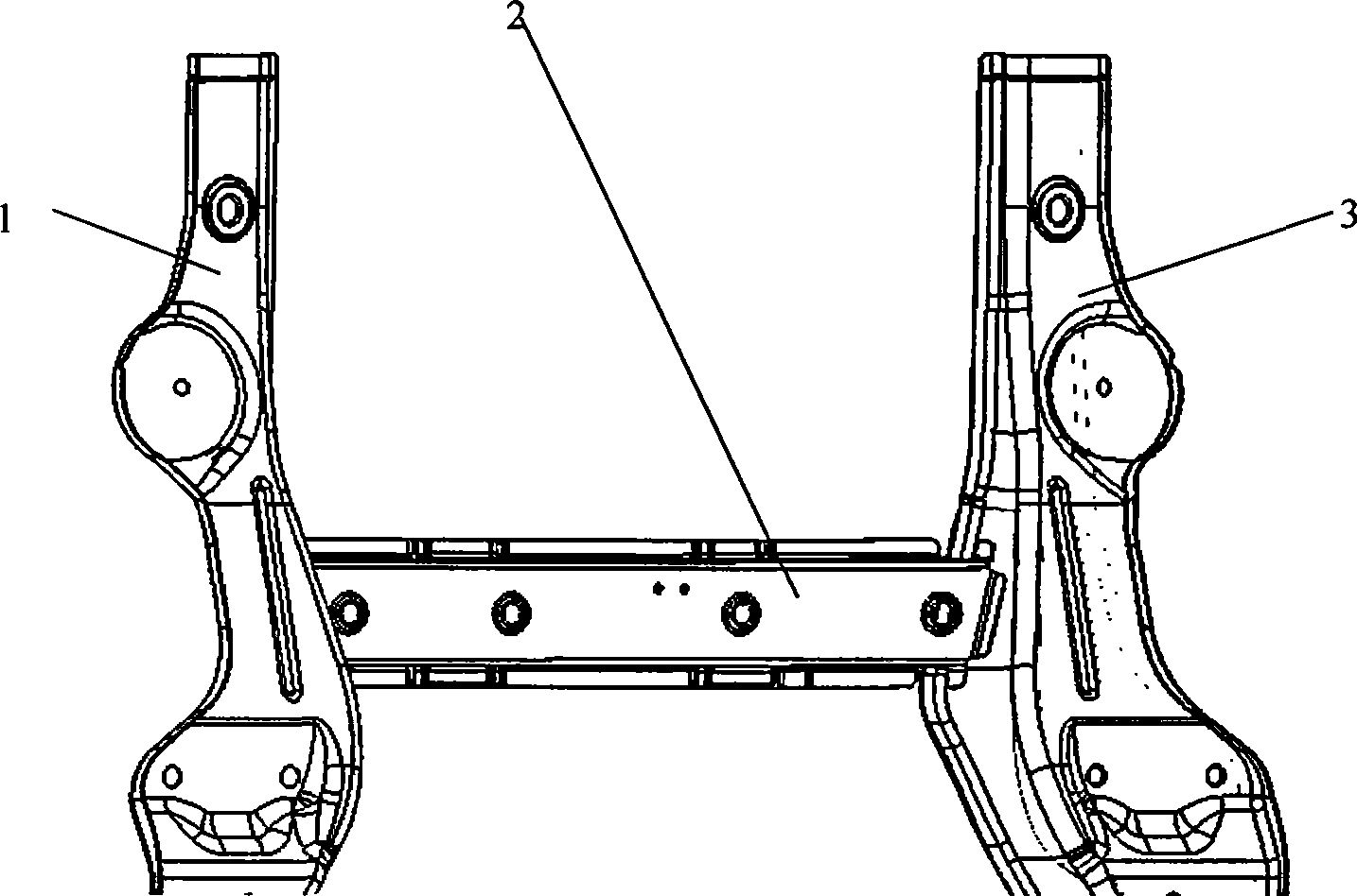
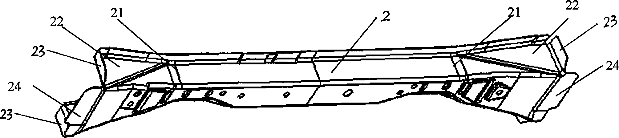
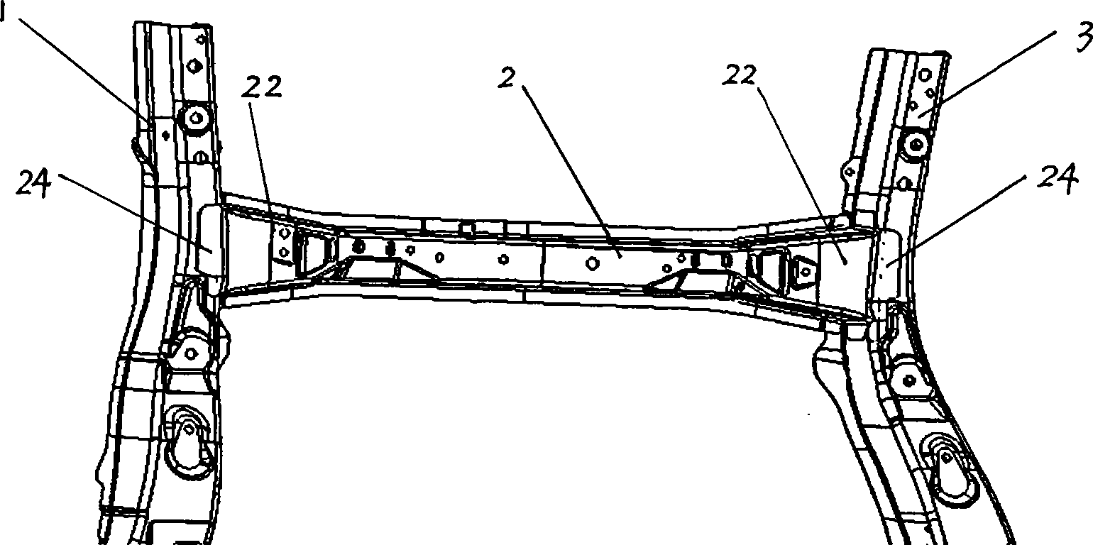
[0009] Such as figure 2 As shown, the cross-beam 2 of the car cross-beam lap structure is a "U"-shaped cross-section part, and the middle of the cross-beam 2 is small. As the cross-beam gradually extends to both ends, the cross-section continues to increase, and a gradually-increasing bell-mouth structure is formed at both ends. 21. The specific position on the beam that gradually increases, that is, the block line 21 in the figure, needs to be finally determined according to the surrounding structure and CAE verification analysis. The end edge of crossbeam 2 is formed with two symmetrical flanging laps 23 and straight edge lapping 24, and two flangings lapping 23 are lapped on the inner surface of left and right longitudinal beam 1 and 3 namely with automobile. On the Z-direction plane based on the coordinate system, the straight side overlapping edge 24 is overlapped on the upper surfaces of the left and right longitudinal beams 1 and 3, that is, on the X-direction plane ba...


PUM


Abstract

The invention discloses a lapping structure of the horizontal beam and the left and right longitudinal beams of an automobile, wherein, the cross section of the horizontal beam is U-shaped and both ends of the horizontal beam are welded crosswise with the longitudinal beams through the lapping edge to form an H shape; both ends of the horizontal beam are flared with the width growing larger and larger. The edges of the end form two symmetrical rolling up lapping edges and a straight lapping edge, wherein, two symmetrical rolling up lapping edges lap on the medial surface of the two longitudinal beams, namely, the surface of the direction of Z subject to the coordinate system of the automobile; the straight lapping edge laps on the upper surface of the longitudinal beams, namely, the surface of the direction of X subject to the coordinate system of the automobile. The invention can successfully solve the problem that the processing kerf at the root of the weld edge and the parts lapping edge easily cracks due to the force transferring effect of the H-shaped lapping structure in the automobile structures and the concentrated stress at the root of the lapping parts, thus guaranteeing the requirement of overall intensity and stiffness of the structure.

Description

technical field [0001] The invention relates to an automobile body structure, in particular to an automobile beam overlapping structure. Background technique [0002] Usually in the design of car body structure, such as figure 1 The shown car body frame cross beam 2 is overlapped with the left and right longitudinal beams 1 and 3 to form an "H"-shaped structure, and the cross section of the car body skeleton cross beam 2 is "U". The way of docking, that is, the two ends of the car body skeleton beam 2 are lapped with three flanges of soybean oil, and the left and right longitudinal beams are overlapped on the Z-direction plane (based on the car coordinate system). In front of the edge, a technological cut must be made. This structure has a poor force transmission effect, and cannot effectively transmit and decompose forces such as side collisions, and the torsion of the car body when driving can easily lead to overlapping edges. Stress concentration at the root of the flan...

Claims


Application Information

Patent Timeline
Patent Type & Authority Applications(China)
IPC IPC(8): B62D21/02
Inventor 向杰张海清刘光英张成勇
Owner CHONGQING CHANGAN AUTOMOBILE CO LTD
Why Eureka
Try Eureka