Comber nipper mechanism

A combing machine and nipper technology, which is applied in the direction of combing machines, textiles, papermaking, fiber processing, etc., can solve the problems of inability to realize constant interval carding, high noise, etc., and is beneficial to the lapping and optimization of cotton webs Control and improve the effect of production environment

Inactive Publication Date: 2011-12-14
DONGHUA UNIV
View PDF0 Cites 0 Cited by
  • Summary
  • Abstract
  • Description
  • Claims
  • Application Information

AI Technical Summary

Problems solved by technology

[0003] The technical problem to be solved by the present invention is to provide a combing machine nipper mechanism to solve the defects in the prior art that combing at constant intervals cannot be realized and the noise is large

Method used


Image

  • Comber nipper mechanism
  • Comber nipper mechanism
  • Comber nipper mechanism

Examples


Embodiment 1

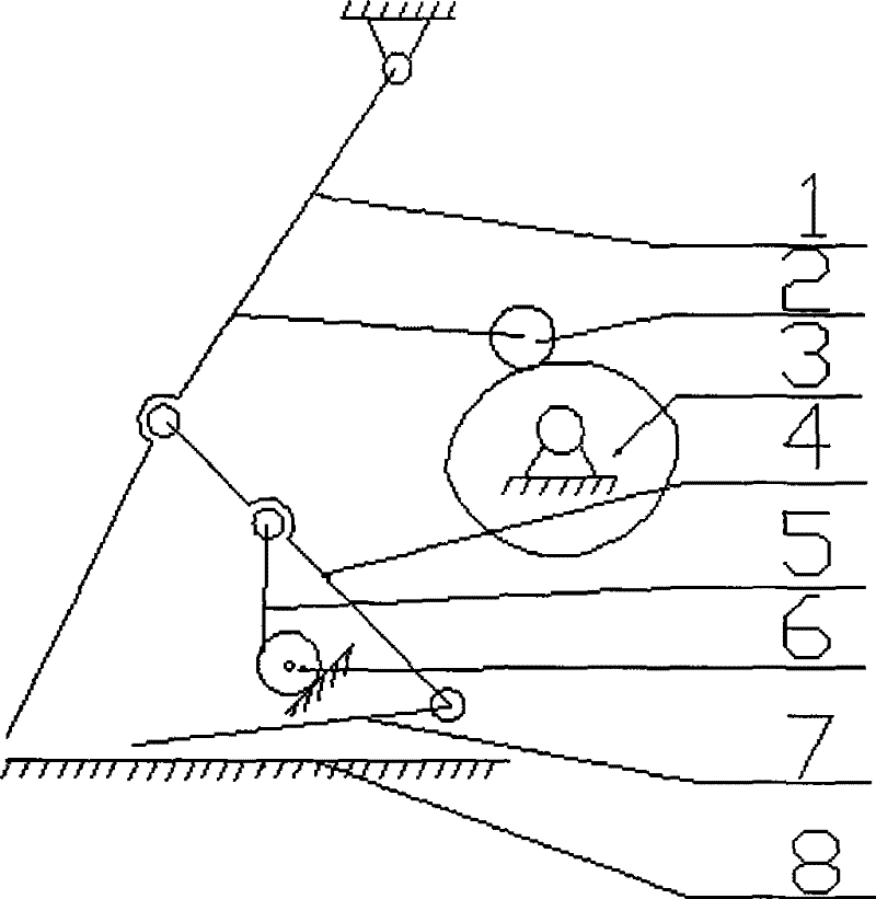
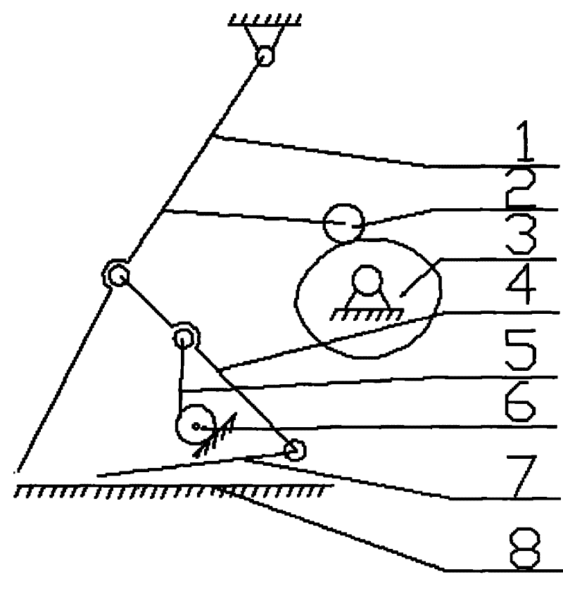
[0013] like figure 2 As shown, a combing machine nipper mechanism includes a motor-driven conjugate cam 3, a swing rod 2 is driven by a driving device 3 and fixed on an upper nipper 1, and one end of the upper nipper 1 is hinged on the frame and the other One end is movable, one end of the connecting rod 4 is hinged on the upper nipper 1 and is located between the joint of the swing rod 2 and the upper nipper 1 and the movable end of the upper nipper 1, and the other end of the connecting rod 4 is hinged to the tongue-shaped piece 7 , The middle part of the connecting rod 4 is hinged with a ratchet 5, the ratchet 5 pushes the ratchet 6 to rotate on the frame, and the lower nipper 8 is fixed on the frame.

Embodiment 2

[0015] like figure 2 As shown, a combing machine nipper mechanism includes a cam 3 driven by a servo motor, a swing rod 2 driven by a driving device 3 and fixed on an upper nipper 1, and one end of the upper nipper 1 is hinged on the frame and the other One end is movable, one end of the connecting rod 4 is hinged on the upper nipper 1 and is located between the joint of the swing rod 2 and the upper nipper 1 and the movable end of the upper nipper 1, and the other end of the connecting rod 4 is hinged to the tongue-shaped piece 7 , The middle part of the connecting rod 4 is hinged with a ratchet 5, the ratchet 5 pushes the ratchet 6 to rotate on the frame, and the lower nipper 8 is fixed on the frame.

[0016] When the present invention is in use, the tongue-shaped piece 7 is linked with the upper nipper 1 . When the upper nipper 1 is opened, the tongue-shaped piece 7 moves to the separating roller, and the cotton web is transported forward, so that the carded cotton web is...


PUM


Abstract

The invention relates to a combing machine nipper mechanism, which includes a driving device, a swing rod (2) is driven by the driving device and fixed on an upper nipper (1), one end of the upper nipper (1) is hinged on the frame and the other One end is movable, and one end of the connecting rod (4) is hinged on the upper nipper (1) between the joint of the fork (2) and the upper nipper (1) and the movable end of the upper nipper (1). The other end of (4) is hinged with the tongue-shaped piece (7), the middle part of the connecting rod (4) is hinged with a pawl (5), the pawl pushes the ratchet to rotate on the frame, and the lower nipper (8) is fixed on the frame superior. The present invention improves the carding effect of the cotton clumps, is more conducive to the lapping of cotton nets, and more importantly, the structure is simple and the transmission chain of the nipper movement system is reduced, and there will be no big noise even under the condition of high mechanical speed , which is conducive to improving the production and operating environment of workers and protecting the health of workers.

Description

technical field [0001] The invention belongs to the field of cotton combing machine parts, in particular to a cotton combing machine nipper mechanism. Background technique [0002] At present, the combing machine nipper driving device all adopts two sets of four-bar linkages of a slider crank linkage and a rocker linkage. like figure 1 As shown, the fulcrum on the gear fixed with the cylinder shaft is hinged with the slider 17, the slider 17 is sleeved on the passive swing rod 16, the passive swing rod 16 is fixed with the nipper shaft 15, and one end of the active swing rod 14 It is hinged with the nipper shaft 15, the other end is hinged with the fulcrum of the lower nipper 13, one fulcrum of the upper nipper 12 is hinged with one end of the swing rod 11 looped on the cylinder shaft, and the other fulcrum is hinged with the middle section of the active swing rod 14 . When the gear is rotated by external force, the nipper swings back and forth under the action of two set...

Claims


Application Information

Patent Timeline
Patent Type & Authority Patents(China)
IPC IPC(8): D01G19/16
Inventor 吴昊郑子明
Owner DONGHUA UNIV
Why Eureka
Try Eureka